
Understanding PLL Applications: Frequency Multiplication
This article explains how a PLL can be used to produce a high-frequency clock from a low-frequency reference signal.
This article explains how a PLL can be used to produce a high-frequency clock from a low-frequency reference signal.
Supporting Information
- What Exactly Is a Phase-Locked Loop, Anyways?
- How to Simulate a Phase-Locked Loop
- Understanding Phase-Locked Loop Transient Response
- How to Optimize the Transient Response of a Phase-Locked Loop
- Designing and Simulating an Optimized Phase-Locked Loop
As you can see in the “Supporting Information” list, I’ve already written five articles on phase-locked loops. I think that these articles provide a thorough introduction to PLL design and functionality, but they are definitely lacking in one respect: they say almost nothing about how PLLs are actually used. The only “application” that we’ve discussed so far is producing a periodic output signal that has the same frequency as a periodic input signal. This, however, is not very impressive since we could do the same thing with a digital buffer or an op-amp voltage follower.
It’s time, then, to discuss real-life PLL applications, and we’ll start with frequency multiplication, which is a natural and intuitive extension of a PLL’s ability to lock onto an input frequency.
Why?
It’s always good to know why you want to do something before you do it. In the case of PLL-based frequency multiplication, we are trying to produce an output waveform with a frequency that is equal to the input frequency multiplied by some constant. This may seem like a somewhat unnecessary task—why not just buy a different oscillator component that directly provides the desired frequency? It turns out that there are various situations in which the PLL approach is quite helpful:
- A system built around a PLL and a low-frequency crystal might reduce cost compared to a system that simply uses a high-frequency crystal.
- With a PLL the multiplication factor can be changed without making any hardware modifications. Thus, many different frequencies can be generated from one oscillator circuit.
- A PLL integrated into a microprocessor can generate a high-frequency clock signal right where it is needed, thus eliminating the complications (I’m thinking of EMI and possible reflections) associated with sending high-frequency signals through PCB traces.
- The frequency-locking characteristics of a PLL make it possible to generate a high-quality (and high-frequency) periodic signal from a low-quality oscillator. To me this is the most important consideration, because it is most representative of a PLL’s core functionality. I would not expect an independent VCO to produce a clock signal with a frequency that can be precisely controlled and that is highly stable over time and temperature. However, the PLL’s locking action allows a VCO to generate a precise and stable clock: if you have, for example, a low-frequency crystal-based oscillator with excellent precision and stability, the PLL will “inherit” this performance—while producing a higher frequency—by locking onto the crystal-based signal.
How?
All you need is a divider:
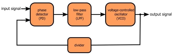
More specifically, you need a divider in the feedback loop, so that the waveform fed back to the phase detector has a frequency that is lower than that of the output signal generated by the VCO.
You may find it somewhat perplexing that dividing the frequency of the feedback signal results in multiplication of the output signal, but this technique is nothing new; in fact, it is completely analogous to what we find in one of the most widely used circuits in electronics, namely, the op-amp-based noninverting amplifier.
Let’s say you have an op-amp configured as a voltage follower. The output is connected directly back to the inverting input terminal, and as a result the op-amp does whatever it needs to do to make the output voltage equal to the input voltage. This is all well and good, but what if we want some gain? Simple, we just use some resistors to turn the feedback loop into a voltage divider:
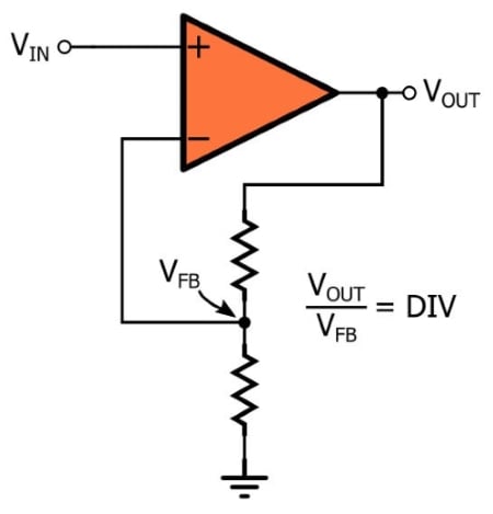
Let’s think about what we’re doing here. The negative-feedback arrangement causes the op-amp to modify its output with one goal in mind: make the voltage at the inverting input equal to the voltage at the non-inverting input. When it’s connected as a voltage follower, this means that VOUT must equal VIN.
But the voltage divider in the feedback loop changes everything. Now, the voltage at the inverting input is DIV times smaller than the voltage at the output. Thus, in order to make the inverting-input voltage equal to the noninverting-input voltage, the output voltage must be DIV times larger than the input voltage.
With an op-amp, then, we create voltage gain by reducing the amplitude of the feedback voltage; with a PLL, we create frequency gain by reducing the frequency of the feedback waveform. To continue the analogy, the gain of a noninverting op-amp circuit is equal to the factor by which the feedback voltage is divided, and the amount of frequency multiplication performed by the PLL is equal to the factor by which the feedback signal’s frequency is divided.
A Quick Example
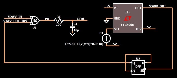
The following circuit is an LTspice version of a phase-locked loop. You are very familiar with this circuit if you have read the preceding articles. This one has a new component, though: I’ve inserted a D-type flip-flop, connected as a divide-by-two counter, into the feedback loop.
Here is a plot that shows the input waveform and the output waveform (after the PLL has achieved lock).
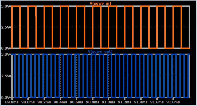
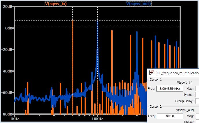
The output waveform and the input waveform have a constant phase relationship (as expected during the locked condition), but the output frequency is significantly higher than the input frequency. We expect the output frequency to be higher by a factor of two, and we can easily confirm that this is the case by looking at the FFT:
Conclusion
After five articles that focused on the fundamental characteristics of phase-locked-loop systems, we have now introduced an extremely widespread practical application of the PLL. By adding a frequency divider into the feedback loop, we can multiply the frequency of an input signal while maintaining the input signal's precision and stability. In the next article we’ll explore additional details related to PLL frequency multiplication.
You can download my LTspice schematic by clicking on the orange button.


Interesting article series about PLL functionality 😊
Hi Robert,
This is very interesting, I’m trying to but the LTspice schematic doesn’t load ... missing XOR_2 and DFF ...