
Understanding Hysteresis in Electronic Components and Circuits
Learn about the behavior and benefits of hysteresis in comparator circuits, magnetic components, and high-power devices.
In two preceding articles, I introduced the concept of hysteresis and elaborated on the way in which the output of a hysteretic system depends on the current state of the input and on the system’s history. In this article, I want to explore some electrical-engineering applications that benefit from hysteresis.
Hysteresis in Comparator Circuits
The comparator circuit is perhaps the most emblematic use of intentional hysteresis in electronic design. As its name suggests, a comparator is a device that compares two input signals and indicates via its output voltage which of the two inputs has a higher voltage.
A basic analog comparator is simply a differential amplifier with high gain, which is why an operational amplifier without negative feedback can make a passable comparator. However, op amps aren’t optimized for comparator functionality, so it’s a much better idea to use a true comparator IC.
An ideal, non-hysteretic comparator has only one differential input threshold. Usually this threshold is 0 V, meaning that the output will transition when the difference between the two input signals is zero. Thus, as soon as the voltage at the non-inverting input rises above the voltage at the inverting input, the output increases rapidly to the comparator’s positive supply voltage; as soon as the voltage at the non-inverting input falls below the voltage at the inverting input, the output transitions to the negative supply voltage.
This all looks pretty good on paper, but in real circuits the single-threshold model is often unsatisfactory. The problem (as usual) is noise. The small-magnitude fluctuations that afflict all real-life signals can lead to multiple output transitions despite the fact that the “true” (which is to say, noise-free) input signals only cross each other one time.
We can see this in Figure 1, where the blue curve represents a signal at the comparator’s non-inverting input. The black line represents a voltage that’s connected to the inverting input and functions as a reference level.
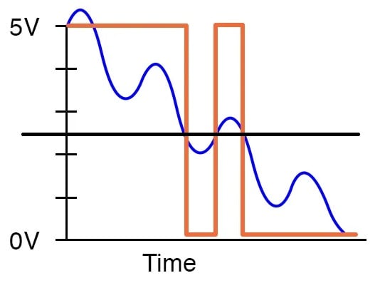
Figure 1. A single-threshold comparator circuit. Image used courtesy of All About Circuits
When the blue curve is well above the reference level, the output is at or near the positive rail. When it’s well below the reference level, the output is at or near the negative rail. The trouble occurs when the blue curve is near the reference level. Since the differential threshold is 0 V, the output transitions every time any sort of crossing occurs. The desired behavior here is only one output transition, because a noise-free version of the blue signal would cause only one transition. With noise, however, we get three transitions.
We can greatly reduce the number of spurious transitions by considering both the current state of the system and the history of the system. In practice, this looks like Figure 2: a comparator circuit in which hysteresis creates two separate thresholds, one for an increasing input signal and one for a decreasing input signal.
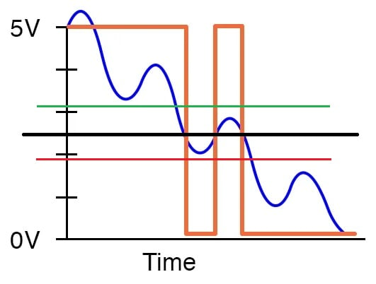
Figure 2. A hysteretic comparator with an increasing input threshold (green line) and a decreasing input threshold (red line). Image used courtesy of All About Circuits and Robert Keim
This diagram demonstrates how the spurious transitions could be avoided if the one reference level were converted into two separate threshold levels, here represented by red and green lines. A transition caused by an increasing signal requires that the input cross the green threshold, and a transition caused by a decreasing signal requires that the input cross the red threshold. This occurs only one time (as indicated by the red circle in Figure 3), and consequently only one output transition is generated.
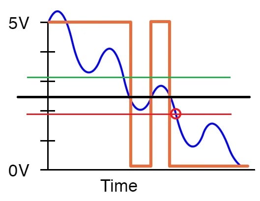
Figure 3. The circuit from Figure 2, with a red circle marking the point where the input crosses the lower threshold. Image used courtesy of All About Circuits and Robert Keim
Hysteresis is achieved by adding positive feedback to the comparator IC. We’ll discuss the circuit design details in the next article.
Magnetic Hysteresis and Data Storage
As I explained in the preceding article, magnetic hysteresis can be either an undesirable source of wasted energy or a beneficial means of suppressing noise. Far more significant within the general history of electronic technology, however, is this: magnetic hysteresis is the underlying principle of data storage in hard disk drives and other magnetic storage media.
Magnetic storage media made possible by ferromagnetic materials, which are naturally hysteretic with regard to magnetic field strength and magnetic flux density. For example, a piece of iron has a hysteresis curve resembling Figure 4.
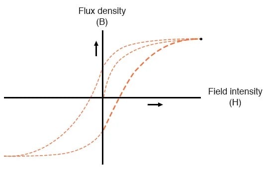
Figure 4. Hysteresis curve for iron. Image used courtesy of All About Circuits
Once a material of this kind has been magnetized, reducing the field intensity to zero won’t reduce the flux density to zero. To remove the magnetization, you actually have to apply a magnetic field of the opposite polarity. Since flux density doesn’t decay to zero when an applied field is deactivated, the material can retain information after power is removed. It can therefore function as nonvolatile memory.
Latching Behavior in Thyristors
I mentioned that we add hysteresis to a comparator by creating a path for positive feedback. A thyristor is a semiconductor device whose internal structure incorporates positive feedback such that it exhibits hysteresis in the form of latching action. Figure 5 shows the physical structure, equivalent circuit, and schematic symbol for a type of thyristor called a silicon-controlled rectifier (SCR).
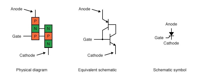
Figure 5. SCR physical diagram, equivalent schematic, and schematic symbol. Image used courtesy of All About Circuits
The TRIAC is a bidirectional version of the SCR. As shown in Figure 6, it’s equivalent to two interconnected SCRs.
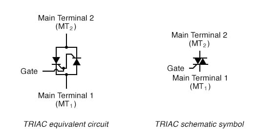
Figure 6. TRIAC equivalent circuit and schematic symbol. Image used courtesy of All About Circuits
SCRs and TRIACs are electrically controlled latching switches. A signal at the gate causes these devices to conduct current, and they continue conducting current after the gate signal has been removed. When the current flowing through the device falls below a threshold called the holding current, it exits the latched state.
This hysteretic behavior is valuable in a variety of higher-power applications. TRIACs are particularly useful in AC applications that must adjust the average power delivered to a load—dimmer circuits, for example.
Up Next
We’ve looked at three examples of hysteresis as a tool for designing and improving electronic circuits. These examples give us a well-rounded idea of the benefits that hysteresis provides—it can make a system more robust against noise, facilitate data storage, and simplify control tasks in high-power and AC systems. I’ll conclude this series on hysteresis with the next article, which will use LTspice simulations to explore hysteresis in comparator circuits.
Background of featured image used courtesy of Adobe Stock


