
How to Troubleshoot a Diode Bridge Rectifier
This article will examine different faults of a diode bridge rectifier to provide some insight into troubleshooting an AC/DC power supply.
This article will examine different faults of a diode bridge rectifier to provide some insight into troubleshooting an AC/DC power supply.
AC/DC power supplies are widely used in different types of electronic equipment. When one fails, how can we determine the cause?
This article will walk you through an example power supply and talk about some possible reasons it could experience failure.
An Example AC/DC Supply
In order to effectively troubleshoot effectively, you'll need to understand your circuit. We'll work with an example AC/DC supply, which converts 230V AC to 5V DC. Its block diagram is shown in Figure 1 below.
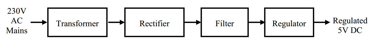
Figure 1. Image courtesy of NUS.
First, let’s first have a brief review of each of these blocks.
Transformer
The transformer converts the high-voltage mains electricity to a lower AC voltage. For example, if we want to generate 12V DC, the transformer may be designed to generate an AC voltage of amplitude 22V as shown in Figure 2.
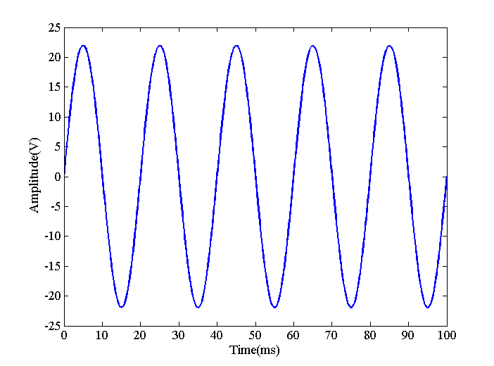
Figure 2
Rectifier
The rectifier converts the AC voltage into a DC voltage as shown in Figure 3. This is done by inverting the negative portion of the AC voltage to generate a positive voltage. The result is a DC voltage because the current can now flow in only one direction through a hypothetical load (not shown in the figure). However, there are still large variations in voltage and current and it cannot be used as a DC supply to power electronic circuits. Figure 3 indicates a very important property of the rectifier output: since the negative portion is flipped to the positive values, the rectifier output is a periodic signal with a period that is half the period of the input. Hence, if the input is a 50-Hz signal, the output frequency will be 100 Hz. This observation can be helpful in troubleshooting an AC/DC power supply.
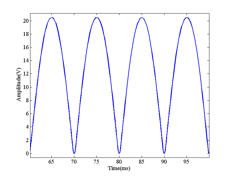
Figure 3
Filter
To get rid of the large fluctuations, we apply a low-pass filter to the rectifier output. The filter will give waveforms similar to the red curves in Figure 4.
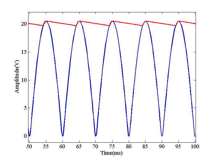
Figure 4
Regulator
Since there are still some ripples, we can apply the filter output to a regulator which uses the feedback concepts to further suppress the fluctuations and generate the desired DC voltage.
Let us examine the faults related to the diode bridge rectifier and the low-pass filter as depicted in Figure 5.
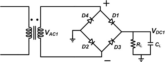
Figure 5
Now that we're familiar with our example, we can start discussing some common issues we may be called upon to troubleshoot.
Issue: A Failed Open Diode
In each half cycle of the $$V_{AC1}$$ input, two of the four diodes will be on. For example, when $$V_{AC1}$$ is positive, D1 and D2 will conduct current while D3 and D4 block (reverse) current. For the next half cycle, D3 and D4 will be conducting. If any of these four diodes has an open-circuit failure, the corresponding half cycle will be omitted and the circuit will act as a half-wave rectifier. Figure 6 shows the effect of a failed-open diode on the output voltage.
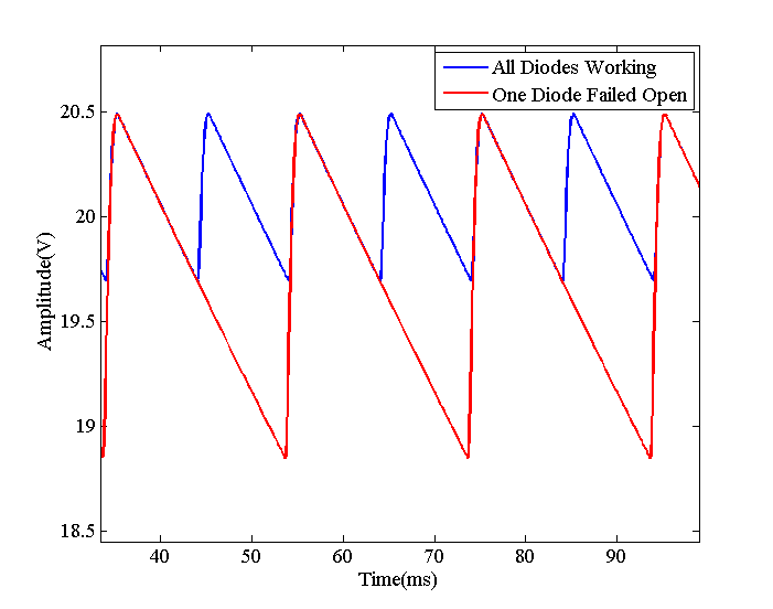
Figure 6
As you can see, the magnitude of the ripples has increased by a factor of about two. Besides the curve related to a failed diode has a period twice the period of the blue curve because the failed circuit is acting as a half-wave rectifier. Therefore, when there is a failed-open diode, the frequency of $$V_{DC1}$$ will be the same as VAC1. With a functioning circuit, the ripples will occur at a frequency twice the input frequency. Using an oscilloscope, we can easily verify the operation of a diode bridge rectifier. If the frequency of the mains electricity is 50 Hz, the frequency of the fluctuations must be 100 Hz. This is an example of the cases in which an oscilloscope is much more helpful than a multimeter.
Issue: A Shorted Diode
In the previous section, we assumed that the diode has an open-circuit failure. However, a failed diode can short out too. In this case, the diode will exhibit a small resistance in both directions. The common reasons for a diode failure are excessive forward current and a large reverse voltage. Usually, large reverse voltage leads to a shorted diode while overcurrent makes it fail open.
Let’s see how a shorted diode will affect a full-wave rectifier. Assume that D1 in Figure 5 is shorted and now the circuit is as shown in Figure 7.
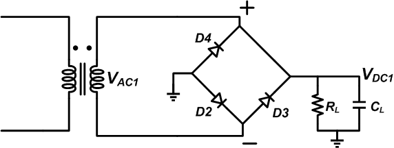
Figure 7
Assume that $$V_{AC1}$$ is positive. In this case, D2 will be on and both D3 and D4 will be reverse biased. The current will flow through the load and the D2 diode back to the secondary of the transformer just as it did in Figure 5. Hence, assuming that the diodes are ideal and have zero forward voltage drop, the positive half-cycle won’t be affected by the shorted diode. But what about the negative half cycle? When $$V_{AC1}$$ becomes negative, D3 will turn on. The current will flow back to the transformer through the shorted diode rather than the load. Hence, $$V_{DC1}$$ will be zero and a large voltage will be directly applied to D3. The excessive forward current may force the D3 to fail open. The transformer and the shorted diode (D1) are the two other components that are likely to burn open.
Issue: Filter Capacitor Aging
AC/DC power supplies generally use electrolytic capacitors to suppress the ripples. These capacitors offer a high capacitance for a given voltage of operation (they have almost the highest available capacitance multiplied by voltage or CV). Besides, this high CV is achieved at an affordable price.
Despite these advantages, the electrolytic capacitors have their limitations. One major drawback is that they have a much shorter life expectancy than other capacitors. This is due to the fact the electrolyte inside the capacitor evaporates over time and the capacitance decreases. By the end of the capacitor lifetime, the capacitance will decrease by about 20%.
It’s also worth to note that the capacitor Equivalent Series Resistance (ESR) increases with use. A larger ESR generates more heat and the heat is the primary factor that can speed up the electrolyte evaporation. This will lead to a thermal runaway situation.
The point is that electrolytic capacitors are probably the first components that will fail in a properly designed electronic system. The designer ignores this reliability issue to simply reduce the costs. With aging, the capacitance will decrease and we’ll have larger ripples on $$V_{DC1}$$. We have used a $$C_L=220 μF$$ and $$R_L= 1 k \Omega$$ to create the graphics of this article. Let’s reduce $$C_L$$ by 20% to visualize the effect of the capacitor aging (we are ignoring the increase in ESR to keep things simpler). With $$C_L=176 μF$$, we obtain the red curve in Figure 8.
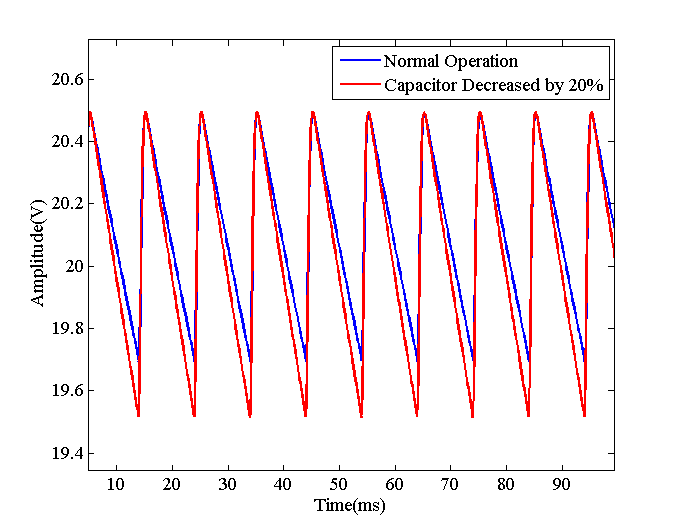
Figure 8
As expected, a smaller capacitor leads to larger fluctuations. Hence, when the ripples are larger than expected, we should examine the frequency of the ripples: if the frequency is twice the input frequency, the diodes are functioning correctly and there’s probably something wrong with the capacitor.
Issue: A Shorted Filter Capacitor
Electrolytic capacitors usually fail open. In fact, the aluminum oxide layer, which forms the dielectric of the capacitor, has self-recovering property and can usually correct a tiny short immediately. However, there are still chances of having a leaky capacitor where a relatively small resistor appears in parallel with the capacitor. If this leakage resistance is so small, the capacitor will seem to be shorted. Applying a reverse voltage to the capacitor can lead to a leaky component. Something that can happen when first manufacturing a board. In this case, the circuit can be modeled as shown in Figure 9.
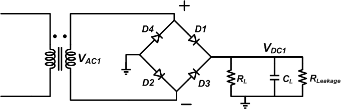
Figure 9
The leakage resistor will make the capacitor discharge faster and so we’ll have larger ripples similar to the red curves of Figure 8. If the leakage resistor is so small, the output will be shorted to ground. Consequently, a shorted capacitor can make the diodes or the transformer fail open.
Conclusion
In this article, we examined different faults of a diode bridge rectifier to provide some insight into troubleshooting an AC/DC power supply. We saw that the frequency of the output ripples can be examined to verify if the diode bridge is functioning correctly or not. Besides, the magnitude of the ripples can give us some clues about the filter capacitor problems.
What other troubleshooting topics would you like to see discussed? Let us know in the comments below.


Could you explain switched mode power supply troubleshooting, please? Your troubleshooting articles are great. Thanks.
Thanks for the article. Clarifies failure of Bridge rectifiers.
Also to note: In practice, 99% of the time, rectifier diodes fail to the shorted state( albeit, the connecting can traces open due to the shorted paths resulting current ). I’ve never seen a diode fail open unless the short condition blasted it.
From the diagram, if either D2 or D4 fail shorted, then usually the other will short as the transformer cycles direction in which the 2nd yet-unblown-diode gets forward biased. This causes the current through it to be excessive since 1st blown diode is now short path to ground. So overall it looks like a dead short to the secondary.