
Electrical Symbols for Electronic Components: Passive Components
This two-article series provides an overview of circuit symbols, along with some information on the components that they represent.
Learn the electrical symbols of basic electronic components, including passive components (resistors, capacitors, inductors, transformers), diodes, and thyristors.
Electrical symbols are a short-hand way of indicating which components are involved in a circuit schematic. They allow for a quick guide to a design for visual communication, an essential aspect of engineering. I can’t imagine a design-review meeting that doesn’t involve a carefully drawn schematic. Despite the proliferation of digital projectors and tablets and whatnot, I suspect that many engineers haven’t found an adequate replacement for physical schematic printouts that can be scrutinized up close and marked with a pencil.
Even if no one else is going to see your design, a good schematic can help you to organize your thoughts, ponder the functionality of a circuit, and find mistakes when they’re very easy to fix (i.e., before the board has been sent to the fab house).
There’s no doubt that some of this information is a bit elementary. However, if you read both articles all the way through, I think you’ll find various details that will be new information for some readers and good reminders for many others.
Note: This guide will focus on North American symbols. If there's sufficient interest from the community, we'll supplement it with symbols popular elsewhere in the world.
Related Information
- Symbols for logic gates, latches, and flip-flops in the AAC textbook
Symbols for Resistors
The general idea of a resistor symbol presents no difficulties, but putting this theory into practice is surprisingly complicated. How many peaks and valleys should there be? Is the first diagonal line directed upward or downward? Should the number of peaks be equal to the number of valleys? What’s the ideal slope of the diagonal lines? There is no current agreed-upon answer to all of these questions across the industry.
Of course, all these questions would be definitively settled if everyone would simply adopt my resistor symbol (which is undoubtedly the best in the world):
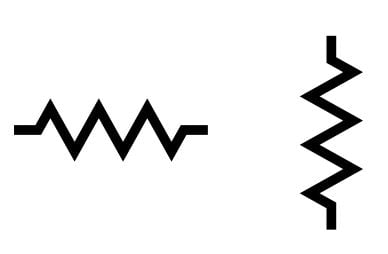
Electrical symbol for resistors
We'll now move on to some components that are extensions of the basic resistor. First, there are resistors that have a non-fixed resistance, rheostats and potentiometers.
Rheostats
If a device is simply a variable resistance, it’s called a rheostat. This is a two-terminal device that allows the user to mechanically adjust the resistance between the terminals.

Rheostat symbol
Potentiometers
A three-terminal variable resistor is a potentiometer. The third terminal (called the wiper) allows the device to function as a variable voltage divider, though a potentiometer can be used as a rheostat by connecting the external circuit to the wiper and one of the other two terminals.

Potentiometer symbol
Photoresistors
Mechanical motion is not the only thing can change the resistance of a component. A variable resistor that is controlled by light is called a photoresistor or an LDR (light-dependent resistor). As you might expect, these devices come in handy when a circuit’s behavior must be influenced by light intensity; take a look at this article for more information.

Photoresistor symbol, AKA LDR
Thermistors
If the resistance of a variable resistor is governed by temperature, we have a thermistor.
As temperature increases, the resistance of an NTC (negative temperature coefficient) thermistor decreases, and the resistance of a PTC (positive temperature coefficient) thermistor increases.

NTC thermistor (left) and PTC thermistor (right)
Symbols for Capacitors
The capacitor symbol, in contrast to the resistor, is very straightforward. The lines at the center of the symbol may be either parallel or curved. When a curved line is used, it indicates the negative terminal.
Ionized capacitors need a plus sign to indicate which side connects to the higher voltage. Even when a curved line is used to show a negative terminal, I recommend using the plus sign, as well. This is so much easier than trying to desolder and resolder an 0402 tantalum cap that the assembly house installed backwards because in a moment of abstraction you mixed up the polarity convention for the curved-line cap symbol.

Electrical symbols for capacitors
Symbol for Inductors
Inductor symbols are even more complicated than resistor symbols. The symbol must somehow evoke a coil of wire. I don’t like the ones that are merely a sequence of drab semicircles, but the extremely loopy versions seem a bit extravagant.
A happy medium may look like this:

Electrical symbol for inductors
I have the impression that some designers consider a ferrite bead to be more or less the same as an inductor. The two components are certainly similar but, in my opinion, they have distinct applications and, consequently, the symbol for a ferrite bead should have something that distinguishes it from an inductor. I don’t think that there are any official guidelines here. My suggestion is the addition of a line or narrow rectangle:

Electrical symbol for ferrite beads
Symbols for Transformers
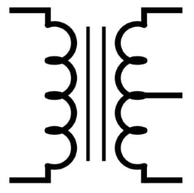
A transformer is similar, in terms of both physical structure and functionality, to two inductors that are placed in close proximity. This fact is effectively conveyed by the circuit symbol, which looks very much like two inductors:

Electrical symbol for transformers
The intense magnetic coupling between these two inductors (called windings when they form part of a transformer) allows for efficient transfer of electrical energy from one winding to the other, despite the fact that there is no direct electrical connection. Thus, a transformer provides galvanic isolation for AC systems. It is also a convenient way to increase or decrease the amplitude of an AC voltage. (You can find more information on this concept on the textbook page for mutual inductance). The vertical lines between the two inductors indicate the presence of a core material; the use of a magnetic core results in a magnetic field that is stronger than what would be obtained if the core were simply air.
What Are the Dots on Transformer Symbols?
Perhaps you’ve noticed transformer symbols that include dots. This is an important detail.
From a structural standpoint, the dots indicate the relative orientation of the windings. From an electrical standpoint, the dots indicate the phase relationship between the input and output signals.
If the windings are wound in the same direction, the input signal is in phase with the output signal. If they are wound in opposite directions, there will be a 180° phase difference between input and output—in other words, the transformer becomes an inverter. This inverting behavior is indicated by dots that are on opposite ends of the symbol.

Transformer dot convention
Center-Tapped Transformers
A variation on the basic transformer theme is the center-tapped transformer. A center tap is a terminal that originates from the center of a winding. This effectively divides the winding into two windings, and each one produces half of the output voltage.
Electrical symbol for a center-tapped transformer
Symbols for Diodes
The basic diode symbol is an intuitive representation of basic diode functionality: the triangle is like an arrow that points in the direction of current flow and the line serves as a barrier to current flow in the opposite direction.

Electrical symbol for a diode
Diodes come in a variety of flavors and, consequently, there are quite a few different symbols.
Zener Diodes
A Zener diode, which functions like a crude voltage regulator when conducting reverse (i.e., cathode-to-anode) current, has the following symbol:

Electrical symbol for a Zener diode
Schottky Diodes
Schottky diodes have a lower forward voltage drop and are useful in circuits, such as switching regulators, in which a diode must rapidly alternate between a conducting state and a nonconducting state. The symbol has a modified line that makes it look like an “S” for “Schottky” (I have no idea if this was the intention).

Electrical symbol for a Schottky diode
Light-Emitting Diodes (LEDs) and Photodiodes
A pair of arrows is used to identify diodes that have functions related to light. The arrows point away from an LED, indicating the generation of light, and they point toward a photodiode, indicating the reception of light.
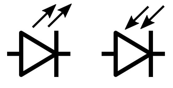
Electrical symbol for an LED (left) and a photodiode (right)
Symbols for Thyristors
Silicon-Controlled Rectifiers (SCRs)
A silicon-controlled rectifier (SCR) is like a diode in that it conducts current only from anode to cathode, but it has an additional terminal, called the gate, that can be used to trigger the device into conduction. Here’s the symbol:

Electrical symbol for a silicon-controlled rectifier
TRIACs
A TRIAC, short for "triode for alternating current", is a type of A TRIAC functions like two SCRs connected in antiparallel—i.e., cathode to anode and anode to cathode. This allows the device to conduct current in both directions (a feature that one could readily infer from the circuit symbol). The gate provides triggering action, as with an SCR.

Electrical symbol for a TRIAC
TRIACs are useful when you need to precisely control AC current, as in this light-dimmer project.
We’ve covered the schematic representations of some of the most common electronic components. In the next article, we’ll look at transistors and mechanical devices.


Good info. Thanks, Robert.
Hello, For a ferrite bead symbol see IEEE 315A, Clause 6.2.11, which is from IEC 60617. The symbol looks like the IEC symbol for a fuse, a rectangle placed over a wire, with one long side removed. This symbol has been around for 33 years in the U.S., since 1986 when IEEE 315A was published, and longer from the IEC publications.
—Regards, Larry