
Introduction to Hysteresis: Rate-Dependent and Rate-Independent Hysteresis
This article, the second in a series on hysteresis, explains two types of hysteresis found in engineered systems.
In the preceding article, I introduced the concept of hysteresis and explained how the output of a hysteretic system depends on both the current state of the input and the system’s history. In this article, I want to provide a more complete theoretical picture by examining the difference between rate-dependent and rate-independent hysteresis. We’ll also look at the relationship between hysteresis and power dissipation.
Lags and Delays
Previously, I cited four definitions of hysteresis. We discussed two of them at the time, and now we’ll discuss the other two:
- “A delay in the change of an observed effect in response to a change in the mechanism producing the effect” —Oxford Dictionary of Electronics and Electrical Engineering.
- “A lagging effect from an expected value due to a resistance such as friction” —Oxford Dictionary of Chemical Engineering.
The delay and lagging effects described here are associated primarily with so-called rate-dependent hysteresis. I say “so-called” because a delayed response could be something as simple as sinusoidal phase lag. In my opinion, that doesn’t qualify as true hysteresis.
Nevertheless, the logic behind this terminology is as follows: rate-dependent hysteresis is dependent on the rate of change—in other words, the frequency—of the input signal. The effects of rate-dependent hysteresis will be more pronounced at certain frequencies.
For example, a low-pass filter causes phase lag. As Figure 1 demonstrates, this phase lag isn’t equal at all frequencies. Instead, the magnitude of the input-to-output phase delay starts at zero and increases as input frequency increases. The phase lag of the low-pass filter therefore represents rate-dependent hysteresis.

Figure 1. Phase lag of a low-pass filter.
Rate-independent hysteresis, which is what we primarily discussed in the last article, creates effects that aren’t influenced by input frequency. An example of rate-independent hysteresis would be a comparator with separate thresholds for increasing input signals and decreasing input signals. These separate thresholds affect output behavior regardless of input frequency.
Reconciling Delay and System History in Hysteresis Theory
The “delay” definitions aren’t at variance with the “system history” definitions, since we can think of rate-independent hysteresis as a more extreme form of rate-dependent hysteresis. Let’s take a look at Figure 2, which reproduces the digital hysteresis diagram from the previous article.
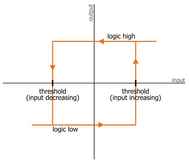
Figure 2. “Digital” hysteresis.
We can see here that the output won’t change state when an increasing input crosses the lower threshold. It also won’t change state at the midpoint between the two thresholds, where we would expect the threshold to be located in the absence of hysteresis. This type of hysteresis creates a delay, but it also creates nonlinear behavior that is far more significant.
For example, let’s say we’re working with logic gates powered by 5 V, with input that starts at 0 V and gradually increases. In the absence of hysteresis, we might expect the threshold to be 2.5 V. But if the gates were designed with hysteresis, the actual thresholds could be 2.25 V and 2.75 V. In that case, the output won’t transition when the input reaches 2.5 V—it has to reach the higher threshold, 2.75 V.
This constitutes a delay in the expected response to an input stimulus. However, we need to recognize that it isn’t just a delay—if the input never reaches the higher threshold, the output will never transition.The output will likewise never transition if the input is decreasing and never reaches the lower threshold.
Hysteresis and Power Dissipation
One of the definitions mentioned above refers to delay caused by “resistance such as friction.” I want to comment on this detail before we finish up.
In mechanical systems, friction is an omnipresent source of unintentional power dissipation. Hysteresis in electrical systems is also a source of “resistance” that leads to wasted energy. For example, consider an AC signal driving a magnetic component such as an iron-core transformer. The signal must supply additional energy in response to the magnetic material’s inherent hysteresis.
A more severe hysteretic tendency requires more of this additional energy. The area enclosed by the two curves in the material’s hysteresis plot corresponds to the amount of unwanted power dissipation.
Actually, though, this power dissipation isn’t always unwanted. The ferrite rings that we see clamped around power-supply or USB cables suppress high-frequency noise because ferrite exhibits strong hysteresis (Figure 3). The interaction between AC noise signals and the ferrite material causes noise energy to dissipate as heat.
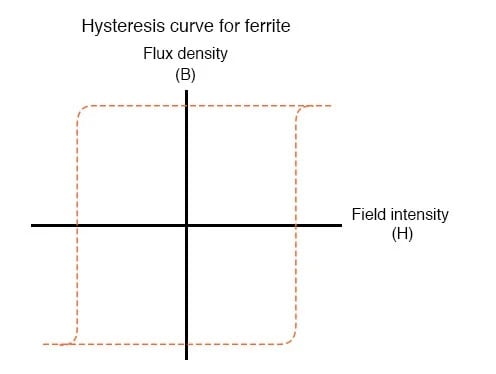
Figure 3. Magnetic hysteresis curve for ferrite.
You can read more about electromagnetism and magnetic hysteresis in Chapter 14 of the All About Circuits electrical engineering textbook.
Up Next
In this article and the previous one, we concerned ourselves with the underlying theory of hysteresis. Next time, we’ll explore the practical implications of hysteresis in electronic circuits.
Background of featured image used courtesy of Adobe Stock; all other images used courtesy of Robert Keim


