
How Is a Load Line Used in Circuit Design?
In this entry of our Frequent Engineering Questions (FEQ) series, learn the basics of how a load line can be used in designing circuits.
This educational brief will describe how a load line affects circuit design and how to analyze a circuit by creating a load from an I-V curve.
Circuit Analysis with Rectifier Diodes, LEDs, and Transistors
Circuits that contain nonlinear components such as rectifier diodes, light-emitting diodes (LEDs), or transistors cannot be comprehensively analyzed using techniques that we typically apply to circuits consisting only of resistors, inductors, and capacitors.
For example, in the following circuit, we cannot precisely calculate the voltage across the diode by combining the two resistors into REQ and then applying Ohm’s law.
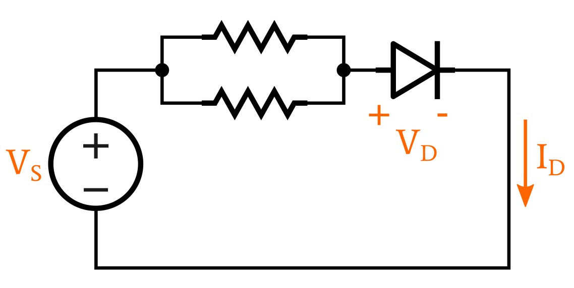
An example diode circuit
In cases such as these, we can perform the required analysis by drawing a graph consisting of a load line and the current–voltage (I–V) characteristic of the nonlinear device.
To create this graph, we first need to know the I–V relationship of the nonlinear device. This information can be obtained from the device’s datasheet, or we can use curves that represent the typical behavior of devices that belong to the general category that we’re interested in—for example, standard silicon diodes or low-voltage NPN transistors.
We then create the load line based on the limits imposed by other circuit elements.
Creating a Load Line from a Diode I–V Curve
In the diode circuit shown above, we know that the diode’s voltage cannot be higher than the supply voltage VS. We also know that the diode current cannot be higher than VS/REQ, because the circuit’s current is limited to this value by the resistors; the diode can further resist current flow and therefore create a value lower than VS/REQ, but it cannot increase current above the level established by the resistors.
Thus, we have a constraint for both the voltage dropped across the diode and the current flowing through the diode. All of the points lying on a straight line between these two constraints represent possible combinations of current and voltage that are possible within the limiting context of the linear elements in the circuit.

A graph showing the intersection of the load line and the diode’s I–V curve
This straight line is what we call the load line.
Only one of these points corresponds to a combination of current and voltage that is possible given the electrical behavior of the diode, which is described by the “diode equation.” We find that one point by marking the intersection of the load line and the diode’s I–V curve, as shown below. The point of intersection corresponds to the circuit’s operating point.
What do you need to learn about load lines? Share your questions in the comments below.


Should we count in the voltage drop across the diode into the current maximum value? Example: (Vs-0.7)/Req
Good introduction.