What Does an Accelerometer Output When It Isn’t Moving? Zero-g Bias
In this article, learn about zero-g offset and zero-g bias level, how it pertains to capacitive MEMS accelerometers, as well as accelerometer offset calibration to trim out offset error.
The list of specifications used to describe an accelerometer is lengthy and sometimes confusing. In this article, we’ll take a look at the “zero-g bias level” and “zero-g offset” specifications of capacitive MEMS accelerometers. We’ll also see how the zero-g offset of an accelerometer can be trimmed out in the end application.
Note: While the common unit of acceleration in physics courses is meter/s2, accelerometer datasheets commonly use the unit of g for acceleration. One g is the nominal gravitational acceleration of an object in a vacuum at the earth’s surface and is approximately equal to 9.807 meters/s2.
What Is Zero-g Bias Level and Zero-g Offset?
Zero-g bias level specifies the sensor output voltage when no acceleration is applied to the device.
The actual zero-g level of an accelerometer can be slightly different from the nominal value. The deviation from the ideal zero-g level is usually specified as a zero-g offset in accelerometer datasheets.
Just as the input offset voltage of an amplifier can introduce error to our measurements, the offset of an accelerometer for zero acceleration can prevent us from successfully interpreting the measured data. Any deviation from the ideal offset value will produce an error. Accelerometer offset is a major concern especially in applications such as inertial navigation systems where the errors accumulate over time and significantly degrade the position accuracy.
In the following sections, we'll illustrate this concept separately for digital-output accelerometers and analog-output accelerometers.
Zero-g Bias Level in Digital Accelerometers
A digital-output accelerometer consists of the circuitry used for an analog-output accelerometer plus an analog-to-digital converter (ADC). In this article, we will refer to them as simply digital accelerometers.
Digital accelerometers commonly output the acceleration data in a two’s complement format. For example, an accelerometer with an 8-bit output and full-scale range of ±2g produces the hexadecimal value of 80 for an input acceleration of -2g.
Table 1 gives a few other examples for the 8-bit resolution case.
Table 1. Data used courtesy of NXP
| Acceleration | Output |
| -2g | $80 |
| -1g | $C1 |
| 0g | $00 |
| +1g | $3F |
| +2g | $7F |
Therefore, when no acceleration is applied to the device, the 8-bit output should be 0000 0000. However, in practice, the output might not be zero.
Digital accelerometers specify the zero-g offset in codes (counts of the least significant bit or LSB).
The following table, Table 2, shows the zero-g level specification of the MMA7456L for different full-scale range settings.
Table 2. Data used courtesy of NXP
| Characteristic | Symbol | Min | Typ | Max | Unit |
| 0g Output Signal (TA = 25°C, VDD = 2.8 V) | |||||
| ±2g range (25°C) 8bit | -18 | 0 | 18 | count | |
| ±4g range (25°C) 8bit | -10 | 0 | 10 | count | |
| ±8g range (25°C) 8bit | -5 | 0 | 5 | count | |
| ±2g range (25°C) 10bit | -18 | 0 | 18 |
count |
With the MMA7456L as an example, the output can be between ±18 counts in 2g mode.
Also, some accelerometers, such as the IAM-20381 from InvenSense, specify the zero-g level offset in mg as shown below in Table 3.
Table 3. Data used courtesy of InvenSense
| PARAMETER | CONDITIONS | MIN | TYP | MAX | UNITS | NOTES |
| ZERO-G OUTPUT | ||||||
| Initial Tolerance | All axes, 25°C | ±50 | mg | 1 | ||
| Zero-G Level Change vs. Temperature | -40°C to ±85°C | ±50 | mg | 1 | ||
This means that the zero-g output typically varies in the range of ±50 mg around the expected ideal value.
Zero-g Bias Level in Analog Accelerometers
With analog accelerometers (that is, accelerometers with analog output) the zero-g bias level is ratiometric and most often midscale relative to the supply voltage (VDD/2).
Table 4, down below, is from the ADXL335 datasheet, which shows how an analog-output accelerometer specifies the zero-g bias information.
Table 4. Data used courtesy of Analog Devices
| Zero-g Bias Level (Ratiometric) | Conditions | Min | Typ | Max | Unit |
| 0 g Voltage at Xout, Yout | Vs = 3 V | 1.35 | 1.5 | 1.65 | V |
| 0 g Voltage at Zout | Vs = 3 V | 1.2 | 1.5 | 1.8 | V |
| 0 g Offset vs. Temperature | ±1 | mg/°C |
With a supply voltage of VS = 3 V, the zero-g bias at the x-, y-, and z-axis outputs is 1.5 V.
Considering the minimum and maximum value of this parameter, the deviation from the ideal value is 150 mV for the x- and y-axis outputs, i.e., the zero-g offset of these two axes is 150 mV.
Zero-g Offset Sources: Mechanical Stress, Temperature, Aging
Accelerometers are factory calibrated for zero-g offset. The calibration values are typically stored in factory programmable registers of the device. On power-up, these calibration values are used to minimize the zero-g offset.
In some applications, the accuracy of the factory calibration is sufficient and there is no need for further calibration in the end application. However, the initial calibration during the manufacturing process might not be sufficient for some other applications.
It should be noted that the zero-g offset can change with the mechanical stress applied to the device.
When the accelerometer is mounted onto the PCB, the board can apply some mechanical stress to the device and change the offset value to some extent. In addition to mechanical stresses from mounting, temperature changes can also alter the zero-g offset value. Accelerometer datasheets specify the zero-g offset variation with temperature in mg/°C.
For example, the datasheet excerpt of the ADXL335 in Table 4 shows that the zero-g offset variation versus temperature is 1 mg/°C for this sensor. Another factor that can change the zero-g offset of an accelerometer is aging.
Due to these variations, demanding applications that need a very low zero-g offset might require additional offset calibration. In these cases, we can use accelerometers that have built-in calibration mechanisms.
Digital Accelerometer Offset Calibration
Some digital accelerometers, such as the MMA8451Q from NXP, allow the user to change the default offset calibration values and trim out the zero-g offset in the end application.
In the case of the MMA8451Q, there are three 8-bit (volatile) offset registers for storing the user offset adjustment values. Each register is used to store the calibration value of one axis. The values stored in these registers are added to the output of the corresponding axis automatically to trim out the offset error.
The calibration values will be lost when power is removed, which is why, in order to avoid recalibrating the system on the next power-up, we can store the calibration values in non-volatile memory on the microcontroller (MCU) and download them into the accelerometer offset calibration registers when the device is turned on.
Trimming Accelerometer Offset Error
To trim out the offset error, we should first measure the zero-g offset of the sensor and store the appropriate value to the offset calibration registers.
To properly calibrate the accelerometer, we need to pay careful attention to the selected measurement range of the sensor and the LSB value of the offset calibration register.
Depending on the selected measurement range of the device, the measured offset value should be divided by an appropriate factor before being stored in the corresponding calibration register. This is because one LSB in the offset register corresponds to a fixed value of acceleration.
With the MMA8451Q, one LSB in the offset calibration register corresponds to 2 mg.
For example, assume that the measured offset at the output of the accelerometer is 9 counts when the ±4g measurement range is selected.
Since the MMA8451Q has a 14-bit output, one LSB of the output corresponds to about 0.5 mg as calculated below:
$$Value\, of\, One\, LSB = \frac{2\times4g}{2^{14}} \simeq 0.5\, mg$$
Figure 5 depicts the 8-bit calibration register and the weight of each bit in this register.
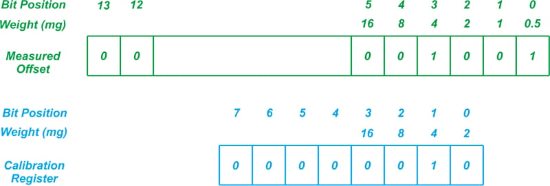
Figure 5. The digital output of the accelerometer (9 counts) along with the weight of each bit position in terms of mg.
The calibration register cannot store values below 2 mg.
Therefore, the two least significant bits of the measured offset that have weights of 1 mg and 0.5 mg cannot be stored in the calibration register and should be discarded. This is why, as shown in the figure, the value stored in the calibration register is 0000 0010 or 2 counts.
Discarding the two least significant bits is equivalent to dividing the measured offset by a factor of 4 and storing the whole part in the calibration register.
In the above example, we have 9 counts divided by 4 which gives 2.25, thus the value stored in the calibration register should be 2.
If a different measurement range is used to measure the zero-g offset of the accelerometer, we have to divide the obtained offset value by a different factor before storing it in the calibration register.
Offset Error Adjustment for MMA8451Q
With that in mind, how much offset adjustment can we have with the MMA8451Q?
The offset register of this accelerometer holds an 8-bit value in 2’s complement format.
Therefore the maximum calibration that can be stored is the largest positive value represented by an 8-bit two’s complement number (+127 counts) multiplied by the weight of the LSB (2 mg) which gives +254 mg.
Similarly, we can determine the largest calibration in the opposite direction. The smallest negative value that can be stored in an 8-bit two’s complement register is -128. Multiplying this by the LSB weight (2 mg) we obtain the largest calibration in the opposite direction which is -256 mg.
Therefore, the maximum calibration that can be achieved with this sensor is about ±256 mg. For more details, please refer to this application note.
Analog Accelerometer Offset Calibration
In many applications, analog-output accelerometers are followed by an A/D converter, which means we can use software to remove the offset error.
However, it is also possible to adjust the offset in the analog domain. Figure 6 shows an example calibration method.
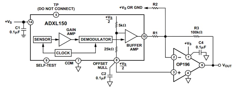
Figure 6. An example block diagram of an analog calibration method. Screenshot used courtesy of Analog Devices.
The resistor R2 connected to the summing junction of the op-amp is used to remove the offset error of the accelerometer. A simple circuit analysis gives the appropriate value of R2.
The other side of R2 connects to either ground or +VS depending on which direction the offset needs to be shifted.
In the above figure, the op-amp is used to amplify the sensor output.
Placing a feedback capacitor in parallel with R3, we can create a 1-pole low-pass filter and limit the accelerometer bandwidth.
For more details, please refer to the datasheet of the ADXL150. This device is obsolete but the circuit design techniques included in the device datasheet can be helpful when working with other similar products.
To see a complete list of my articles, please visit this page.