
An Introduction to Current Sources
Current sources are less familiar than voltage sources like batteries and AC wall power. Current sources usually are buried, unseen, inside electronic circuitry. Learn what they are and how they are designed.
Most of us understand voltage sources. Whether you plug only one device or several devices into your wall outlets, the voltage stays the same. When you put two or three batteries in series, you double or triple the voltage.
Measuring voltage is easy. If you have a voltmeter, set it to the proper scale and put the two probes into the wall outlet (carefully, of course) or across the battery.
Current, however, is less familiar. Even some technical people don’t really understand current or know how to measure it. Even fewer understand current sources or even know they exist. In this article, let’s quickly review the basics of current before jumping into current sources.
Voltage vs Current
Diving in, let's look at Figure 1, which compares electric current to water flow.
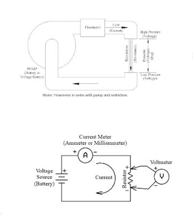
Figure 1. Water flow is analogous to electric current.
Voltage is the pressure generated by the pump, and current is the flow. Adding a resistance (restriction) reduces the current (flow). If the circuit is broken (pipe is blocked), there still will be voltage (pressure) but no current (flow).
To measure water flow, a flowmeter is added in series in the pipe. Likewise, to measure current, an ammeter is added in series, as shown in Figure 2.
Figure 2. Current measurement requires the meter to be connected in series, not parallel.
The circuit must typically be broken (a wire cut or a connection opened) to add the meter. This is different from voltage, which can be measured by just touching the meter probes between the two measurement points.
As an aside, there are clamp-on current meters that wrap around a wire and measure current indirectly by measuring the wire’s magnetic field. These do not require breaking the circuit. These are analogous to clamp-on flowmeters that use an ultrasonic beam to measure water flow.
Current Source vs Voltage Source
Next, take a look at Figure 3, which compares voltage and current sources.
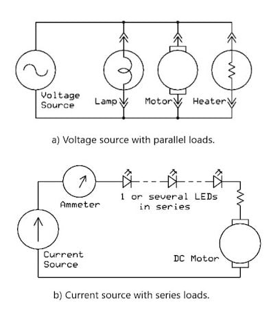
Figure 3. Voltage loads are connected in parallel (a), while current loads are in series (b).
Adding loads in parallel to a voltage source increases the current but does not change the voltage unless the total current is more than the source (generator or battery) can supply.
In the example of a current source, shown in Figure 3b, the loads are added in series. If additional light-emitting diodes (LEDs) are added, the resistance changes. If the motor is removed (replaced with a short circuit), the voltage will change, but not the current. The current will stay constant unless the total load voltage exceeds what the current source can supply.
Current Source Applications
Current source circuitry is widely used in industrial control systems. Current, rather than voltage, is used to transmit analog measurements over long distances. Current transmission has advantages over-voltage signals. The current is not affected by the added resistance of long wiring. Also, current signals are less apt to be affected by electrical noise or electromagnetic interference (EMI).
Industrial Two-wire Transmission
In industrial applications, an elevated-zero signal with a current range of 4 to 20 mA DC is typically used. The elevated-zero signal means that 4 mA represents the low (typically zero) end of the range. The high, full-scale end of the current range is 20 mA. For example, 4 to 20 mA might represent 0 to 250 degrees from an angle position sensor. Figure 4 shows a typical 4–20 mA industrial current communication system.
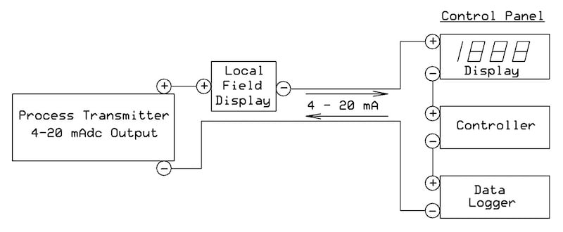
Figure 4. A typical industrial 4-20 mA current loop to transmit measure signals.
Another advantage of current sources is that, in some systems, power can be sent over the same two wires as the current signal. Industrial two-wire transmitters control the current in the loop to be proportional to the measurement and “steal” their operating power from the loop current.
Current Source and LED Drivers
LEDs are often driven by current sources. As mentioned above, one, two, or several LEDs can be wired in series, and the current will not change. The current sources usually are specialized LED driver ICs, not simple circuits you can design yourself. Often, they use pulse width modulation (PWM) to maintain efficient operation with changing loads and supply voltages. Many are available, with varying features for different applications.
To learn a bit more, here are links to a simple IC from Diodes Inc. and one from onsemi.
Currents Sources in Integrated Circuits
Current sources are also used in the internal circuits of ICs, especially analog circuits. The current sources are also referred to as current mirrors. Popular current mirror designs include the Widlar current source, named after the legendary analog designer Bob Widlar.
How to Design a Current Source?
Take a look at Figure 5, which illustrates a simple, one-transistor current source circuit.
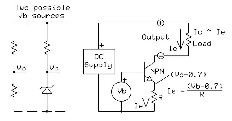
Figure 5. One-transistor current source.
Due to the base-emitter voltage drop of the NPN transistor, the emitter voltage is about 0.7 volts below the base voltage (Vb). The emitter current, Ie, equals Ve/R. The collector current will be constant, approximately equal to Ie, regardless of the voltage on the collector. Overall, it will be roughly one percent lower due to the slight current drawn through the base.
The circuit is sometimes called a current sink because it draws or sinks current from the supply. To change it to a source, replace the NPN transistor with a PNP transistor and turn the circuit upside down, connecting the minus output to the common.
If Vb is variable, Ie and Ic will vary proportionally. Figure 5 also shows two possible fixed voltage sources. The one using two resistors will vary if the supply voltage varies, causing the current to change. The Zener source will remain constant despite supply voltage changes.
Precision 4-20 mA Source for Industrial Process Measurement
Figure 6 adds an op-amp to create a precision voltage-controlled 4–20 mA current source.
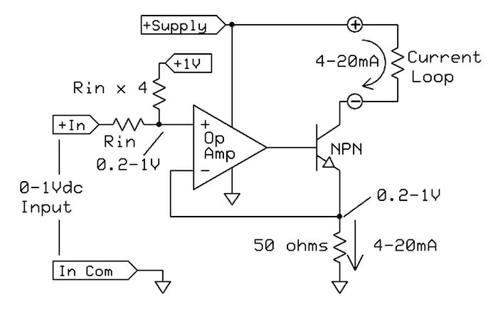
Figure 6. Precision 4-20 mA source.
The 0–1 VDC input might be an amplified measurement signal from a thermocouple, strain gauge, or other transducers. The two input resistors convert it to 0.2-1.0 V, creating the 4 mA output offset. Op-amp feedback holds the emitter output equal to the 0.2–1.0 V input. The 50 Ω resistor converts this to the 4–20 mA output current.
The circuit, as shown, will be less than completely accurate due to the typical +/-1% tolerances of the resistors, variation of the 1 V supply, and the slight difference between the emitter and collector currents.
Figure 7, on the other hand, shows a practical version that adds gain and offset trim adjustments and uses a 5 V reference.
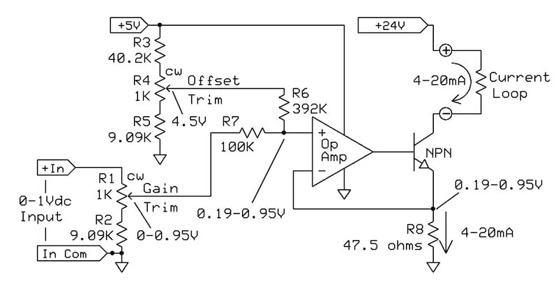
Figure 7. Improved 4-20 mA circuit with precise adjustment of gain and offset.
The op-amp does not need more than 5 V to operate. The 24 V output supply supports output resistance up to about 1100 Ω (22 V at 20 mA), but a lower voltage may be used at a lower resistance.
The op-amp specifications are not critical. The transistor’s maximum power happens at low output resistance: 0.48 W (24 V at 20 mA) if the load is zero ohms. It should be rated for at least 1 W to safely handle currents exceeding 20 mA.
Other Current Source Designs
There are several other ways to design a current source. Below are a few examples, including some described in detail by previous All About Circuits articles:
- An example using a MOSFET current source (FET current mirror)
- An example using a junction transistor current mirror
- A current source is made using a voltage regulator IC
- An article using op-amp circuitry to design a voltage-controlled, bidirectional output current source
Aside from these articles, you can also an example of a current source IC, the LM134/LM234/LM334, which is available from several manufacturers.
Summarizing Current Sources
To summarize quickly, current sources are less widely understood than voltage sources. Current sources generate a current that is unaffected by changes in the load. They’re widely used to send analog process signals over long distances, to light LEDs, and in internal IC circuitry. In this article, we’ve reviewed the basics and shared several different design approaches.


The transistor based current sources would be more accurate if a MOSFET were used. The emitter current is the collector current plus the base current in the transistor based examples shown. There wouldn’t be base-current error if a MOSFET were used.
While I do understand what this is about, I wish very much that engineer’s were more averse to using terminology that amounts to jabberwocky. I don’t know who it was who first came up with the terminology “current source”, but I wish that whoever is responsible for this had had sense enough to realize that it is an exceedingly poor name to use. After all, a DC battery is a source of current, is it not? I just disdain jabberwocky, and this is one of the most egregious examples of jabberwocky that I know of. Engineers need to apply better judgement when they think about what they are going to call something. If you don’t understand my point, try thinking about how difficult it is to explain to someone else exactly what a “current source” is. The explanation offered here is decidedly poor, the same as most every other attempt that anyone makes to try and make sense of this very contrived concept. The language encountered in such efforts is almost always jabberwocky. Here, for example, we find this: “Adding loads in parallel to a voltage source increases the current but does not change the voltage unless the total current is more than the source (generator or battery) can supply.” How is this not jabberwocky? The statement implies that current can be greater than it can be. I don’t like saying it, but anyone who isn’t able to avoid this kind of thing when trying to explain something should simply not attempt to explain things. The paragraph that follows that statement is even worse. It reads: “In the example of a current source, shown in Figure 3b, the loads are added in series. If additional light-emitting diodes (LEDs) are added, the resistance changes. If the motor is [...] replaced with a short circuit, the voltage will change, but not the current. The current will stay constant unless the total load voltage exceeds what the current source can supply.” By inference, the definition of a current source is a circuit where multiple loads are connected in series. I’m entirely certain that this misses the target by a wide margin. And where the statement says, “the voltage will change”, shouldn’t the statement be clear about which voltage it is that changes? Moreover, that sentence as written implies a violation of Ohm’s law. It says that voltage (some voltage ...) will change but that current will not. Since when is this possible? And how would it possibly make a whit of sense to say something that implies that total voltage drop across a series load can exceed the voltage supplied by the voltage, i.e., how would it make sense to imply that the voltages in a closed electrical loop do not sum to zero? When you attempt to explain something and in doing so you make a number of statements that are contrary to the fundamental laws of electricity, you are not doing any service to anyone.
In the example of a current source, shown in Figure 3b, the loads are added in series. If additional light-emitting diodes (LEDs) are added, the resistance changes. If the motor is removed (replaced with a short circuit), the voltage will change, but not the current. The current will stay constant unless the total load voltage exceeds what the current source can supply.
Hi,
This article is about current sources, but the transistor-based example shows a current sink. The text add that it can be transformed to a current source just using a PNP transistor and uside-down the circuit. That’s not as simple doing it. Would’nt it be easier to understand the circuit showing directly an example with a PNP transistor? I tried to imaging the circuit without exit. Should the formula be changed to compute the current value?
Thanks