
Introduction to Adaptive Front Lighting Systems (AFS)
Learn more about the design considerations that go into developing adaptive automotive lighting solutions.
Today’s vehicles try to optimize the nighttime vision by dynamically adjusting the headlights. In this article, we’ll first take a look at the advantages of this technology. Then, we’ll briefly examine the design challenges and the main building blocks.
Introduction
Adaptive front lighting systems (AFS) attempt to dynamically adjust the headlights of the vehicle so that the driver has optimum nighttime vision without compromising the safety of other road users. The AFS uses stepper motors to control the headlight angle when the vehicle steers or the road is not even. Besides, the adaptive system tries to avoid a direct glare to oncoming vehicles. It uses headlights that consist of an array of LEDs.
Depending on the position of the oncoming car, some of these LEDs are automatically dimmed. In this way, while around the oncoming car is illuminated, the driver side is dimmed. The AFS uses image sensors to detect the position of the oncoming vehicle. Figure 1 shows how the AFS adjusts the headlights to dim the driver side of the oncoming car.
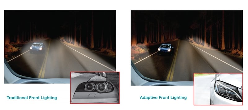
Figure 1. Image courtesy of TI.
Similarly, the AFS avoids blinding the driver of the preceding car by not directly shining onto its rear-view mirror.

Figure 2. Image courtesy of ON Semiconductor
The AFS consists of several different building blocks, such as LED drivers, LED matrix managers, stepper motors, imaging sensors, MCUs, etc. To efficiently control the light intensity and direction, these blocks should be fast, efficient and accurate. Let’s briefly examine the design challenges and the main building blocks of the AFS.
LED Driver for Automotive Applications
The functionality of the AFS depends on producing complex light patterns at a fast rate. LEDs exhibit an illumination rise time about two times faster than that of incandescent sources. Besides, LEDs are more power-efficient and offer a superior clarity of white light. Due to these advantages, they are widely utilized in the automotive industry. To produce the light patterns required by the AFS, we can incorporate an array of LEDs in the headlight and selectively turn some of them on.
To operate the LEDs, we need special circuitry referred to as LED drivers. The driver should provide the LEDs with a constant current to preserve the light color. Figure 3 shows the structure of an LED driver for automotive applications.
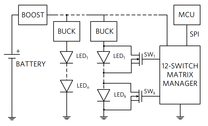
Figure 3. Image courtesy of Maxim Integrated.
While the car battery voltage should be typically about 12 V, it can go as low as 6 V at times. This low, unregulated voltage cannot be directly used for powering the LEDs. That’s why we need a boost converter after the battery. The output of the boost converter, which is regulated and sufficiently high, is used to power the buck converters that are connected to strings of LEDs. Each LED string is used for a different headlight functionality, such as high beam, low beam, turn, position, fog, etc.
And, each LED string requires a different current. The buck converter acts as an ideal current source and keeps the current through the LED strings constant. In this way, the light color is preserved. Moreover, the buck converters can exhibit a better immunity to LED open or short failures. Figure 4 shows the LED driver and some additional details of the front lighting system.
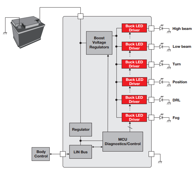
Figure 4. Image courtesy of TI.
LED Matrix Manager
The driver should provide the LEDs with a constant current to preserve the light color. However, we still need to dim some of the LEDs to create the different light patterns required. To this end, the concept of pulse-width modulation (PWM), shown in Figure 5, can be used. As you can see, the pulse width is varied to adjust the LED intensity.
When the pulse is high, the constant current produced by the LED driver is applied to the LED. When the pulse goes to low, the current gets cut off. In this way, while the current applied to the LED is almost constant, we can change the pulse duty cycle to adjust the light intensity.

Figure 5. Image courtesy of Sparkfun.
Unfortunately, even when we dim the light from 100% to 50%, the human eye cannot detect a significant change in light intensity. That’s why the LED driver should change the PWM duty cycle by a large ratio. For example, the LT3952 is capable of a 300:1 PWM dimming ratio. The array of switches used for individually switching the LEDs on/off can be placed in parallel with the LEDs as shown in Figure 3. Figure 6 shows another example, the TPS92661 LED Matrix Manager, from TI. You can find some additional details in this figure.

Figure 6. Image courtesy of TI.
Stepper Motors
The AFS uses fast, accurate stepper motors to adjust the lamp positions depending on the information gathered from different sensors such as the steering wheel position, the car speed, pitch and an oncoming vehicle. An example schematic for driving a stepper motor for AFS applications is shown in Figure 7.

Figure 7. Image courtesy of ON Semiconductor.
The AFS stepper motors need to be reliable and fault-tolerant to avoid any unsafe driving conditions. Besides, it is important to take precautions for motor overload stall detection. The stall condition can be detected by monitoring the phase relationship between the motor winding current and the back-EMF. This is illustrated in Figure 8.

Figure 8. Image courtesy of TI.
As the motor load increases at a given winding current, the phase shift between the winding current and the back-EMF decreases. Many stepper motor drivers use this phenomenon to detect a stall condition. The ON Semiconductor’s NCV70522 can even indicate the back-EMF at an external output. This can be useful for AFS application if we need to adjust the stall detection level depending on the driving conditions.
AFS Controller
To generate the instructions for the different building blocks of the AFS such as the LED Matrix Manager and the stepper motors, we can use microcontrollers such as those from TI’s TMS470M safety microcontroller family. This family is based on ARM® Cortex™-M3 CPU and runs at 80 MHz. It supports features such as CAN, LIN and high-end timer (HET) for PWM generation. Besides, it has built-in safety features that make it suitable for safety-critical applications with lower performance needs. The mentioned TI document presents a reference design for AFS.
Conclusion
In this article, we first looked at the advantages of the AFS. Also, we briefly examined the design challenges and the main building blocks. The AFS incorporates features that are interesting to both car buyers and legislators. Moreover, it provides engineers and companies with a great opportunity to create innovative products for AFS (and automotive night-vision systems) applications.


Very impressive article. Keep on sharing.