
Accelerometer Specifications: Measurement Range, Sensitivity, and Noise Performance
Learn about capacitive MEMS accelerometer specifications for measurement range, sensitivity, and noise performance for both digital- and analog-output accelerometers.
The list of specifications used to describe an accelerometer can often be lengthy and sometimes confusing. In previous articles in this series, we discussed the frequency response, bandwidth, and zero-g offset of MEMS accelerometers.
In this article, we’ll take a look at some other important specifications that are commonly used to describe capacitive MEMS accelerometers.
Accelerometer Measurement Range: Acceleration Amplitude
This specification provides the range of acceleration amplitude the part can measure.
Measurement range is typically expressed in ±g. For example, the measurement range of the ADXL335 is ±3g. Within this range, the device has a linear input-output relationship.
A digital-output accelerometer typically provides several different measurement ranges. For example, the MMA7456L has ±2g, ±4g, ±8g modes of operation.
As we’ll see below, the measurement range and sensitivity specifications are related to each other. The sensitivity of a digital accelerometer decreases as we program the device to operate at a larger measurement range.
When choosing an accelerometer, it's important to not underestimate the acceleration range of the application.
Some technical documents suggest using an accelerometer with a measurement range 5x larger than the expected range of the application to ensure ample margins for measuring unpredicted or unexpected accelerations. Also, the measurement range should not be confused with the “Absolute Maximum Acceleration,” which specifies the acceleration level that can cause damage to the part.
The absolute maximum acceleration of the ADXL335 is 10,000g whereas its measurement range is only ±3g.
Analog and Digital Accelerometer Sensitivity
Sensitivity is the ratio of the change in the accelerometer output to the change in the applied acceleration. The sensitivity of an analog-output accelerometer is typically specified in mV/g. For example, in Table 1, the sensitivity of the ADXL335 from Analog Devices is 300 mV/g.
Table 1. Data used courtesy of Analog Devices
| Parameter | Conditions | Min | Typ | Max | Unit |
| Sensitivity (Radiometric)2 | Each axis | ||||
| Sensitivity at XOUT, YOUT, ZOUT | VS = 3 V | 270 | 300 | 330 | mV/g |
| Sensitivity Change Due to Temperature3 | VS = 3 V | ±0.01 | %/°C |
Note that sensitivity is ratiometric.
The ADXL335 datasheet gives the device sensitivity for a supply voltage of 3 V. If we operate this sensor with a 3.6 V power supply, its sensitivity will be 360 mV/g.
Accelerometer datasheets also specify the sensitivity variation with temperature as a percentage shift per °C. This temperature dependency is caused by the circuit temperature coefficients as well as the fact that the properties of the mechanical components of the accelerometer change with the temperature-induced mechanical stresses.
The sensitivity of a digital-output accelerometer is typically expressed in counts per g. For example, the sensitivity specification of the MMA7456L for different full-scale range settings is as given in Table 2 below.
Table 2. Data used courtesy of NXP
| Characteristic | Symbol | Min | Typ | Max | Unit |
| Sensitivity (TA = 25°C, VDD = 2.8 V) | |||||
| ±2g range (25°C) 8bit | 58 | 64 | 70 | count/g | |
| ±4g range (25°C) 8bit | 29 | 32 | 35 | count/g | |
| ±8g range (25°C) 8bit | 14.5 | 16 | 17.5 | count/g | |
| ±8g range (25°C) 10bit | 58 | 64 | 70 | count/g |
Note that for a given number of bits at the output, the sensitivity halves as we double the measurement range.
Noise Performance and Power Spectral Density: Analog-output Accelerometers
The output of an accelerometer is affected by two different types of noise: the thermo-mechanical noise of the moving parts and the electronic noise generated in the signal conditioning circuitry of the accelerometer.
Datasheets characterize the overall noise performance of the accelerometer by giving the noise “power spectral density” (PSD) in $$\frac{\mu g}{\sqrt{Hz}}$$.
For example, the ADXL335 has a PSD of 150 $$\frac{\mu g}{\sqrt{Hz}}$$ in the x- and y-axis outputs as shown below in Table 3.
Table 3. Data used courtesy of Analog Devices
| Parameter | Conditions | Min | Typ | Max | Unit |
| Noise Performance | |||||
| Noise Density XOUT, YOUT | 150 | μg/√Hz rms | |||
| Noise Density ZOUT | 300 | μg/√Hz rms |
The PSD gives us insight into how the average power of the noise is distributed in different frequency bands. Assuming that a single-pole filter is used to set the system bandwidth, we can find the RMS (root square mean) value of the noise by applying the following equation:
$$RMS\,Noise = Noise\,Density \times\sqrt{BW \times 1.6}$$
where BW is the bandwidth of the single-pole RC filter and is given by:
$$BW = \frac{1}{2\pi \times R \times C}$$
In this equation, R and C denote the filter resistor and capacitor values.
Assume that the filter bandwidth at the x-axis output of the ADXL335 is 200 Hz. In this case, the RMS value of the noise is equal to 2.683 mg.
With a probability of 0.9973, we can assume that the noise peak-to-peak value is less than or equal to six times the RMS value, giving a peak-to-peak value of 16.098 mg. The peak-to-peak value of the noise gives us a sense of the smallest detectable acceleration.
For example, it is not a good idea to use a system that exhibits a peak-to-peak noise of about 16 mg when the lowest acceleration level we need to measure is 5 mg. Such a small signal will be obscured by the noise floor of the system.
Some technical documents suggest that the smallest detectable acceleration required by the application be at least 10x larger than the RMS noise of the accelerometer.
Noise Performance: Digital-output Accelerometers
Understanding the noise performance of a digital-output accelerometer and determining the minimum detectable acceleration of these devices can be a bit more challenging than analog-output accelerometers. Let’s take a look at the MMA8451Q as an example.
The 14-bit MMA8451Q has a PSD of 126 $$\frac{\mu g}{\sqrt{Hz}}$$ in its normal mode of operation (the device also has a low-noise mode). If we set the measurement range of this accelerometer to ±2g, what is the minimum detectable acceleration?
In this case, the total 4g range is divided into 214 discrete levels and hence, one LSB (least significant bit) of the output code corresponds to about 0.25 mg.
One might mistakenly conclude that the device can detect acceleration levels as small as 0.25 mg. However, the important point is that some of the output bits might be corrupted by the system noise. In fact, the analog signal delivered to the A/D converter might have a noise floor much higher than the LSB value. Thus, we need to evaluate the noise performance and determine how many bits at the output are noise-free.
To this end, we need to examine the noise performance of the device. The PSD specified in the MMA8451Q datasheet includes the thermo-mechanical noise of the moving parts and the electronic noise generated in the signal conditioning circuitry up to the A/D converter (Figure 4).
The provided noise PSD doesn’t include the ADC quantization noise.
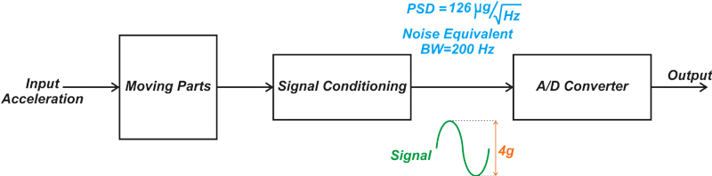
Figure 4. An example diagram showing the noise created from input acceleration to the output.
Assume that the noise equivalent bandwidth of the system is 200 Hz. In this case, the RMS value of the noise at the input of the ADC is given by:
$$RMS\,Noise = Noise\,Density \times \sqrt{Noise\,Equivalent\,BW} = 126 \frac{\mu g}{\sqrt{Hz}}\times \sqrt{200\,Hz} = 1.782\,mg$$
The digitization process also adds some quantization noise to the signal. However, the RMS value of the ADC quantization noise is equal to $$\frac{LSB}{\sqrt{12}} = 72.1 \mu g$$
This is about 25x smaller than the noise coming from the upstream blocks, which can be neglected.
Assuming that the desired signal at the ADC input is a sinusoidal with a peak-to-peak value of 4g, the RMS value of the desired signal is $$\frac{4g}{2\sqrt{2}}$$ and hence, we obtain the signal-to-noise ratio (SNR) as given by:
$$SNR = 20log_{10}\left( \frac{Signal\,RMS\,Value}{Noise\,RMS\,Value} \right)= 20log_{10}\left(\frac{\frac{4g}{2\sqrt{2}}}{1.782\,mg} \right) \simeq 58\,dB$$
Equation 1.
The SNR of an ideal N-bit ADC is given by the following well-known equation:
$$SNR = 6.02N + 1.76$$
Substituting the SNR we calculated in Equation 1 into the above equation, we can find the effective number of bits of the converter:
$$N_{\,effective} = \frac{SNR-1.76}{6.02} = \frac{58-1.76}{6.02} = 9.34\,bits$$
Therefore, we can assume that the total 4g range of the accelerometer is divided into 29.34 discrete levels, which means the minimum acceleration level that the system can detect is:
$$Minimum Detectable Acceleration = \frac{4g}{2^{9.34}} = 6.1\,mg$$
As you can see, this is significantly larger than the LSB value of the employed 14-bit ADC. It is worthwhile to mention that the MMA8451Q offers several different oversampling schemes that can increase the device resolution at the cost of higher power and slower reaction time.
For more details about calculating the effective number of bits of the MMA8451Q and the oversampling modes of this device, please refer to the application note “How Many Bits are Enough?” from NXP.
To see a complete list of my articles, please visit this page.
Featured image used courtesy of Analog Devices


