The 16 Boolean Logic Functions of Two-Input Systems
Learn about all 16 possible logic functions that can be realized for two binary inputs.
Boolean logic has been ruling the world of computational digital systems for many decades. Nonetheless, a few logic functions have been overlooked considerably.
In this article, I make an attempt to shed light on some of the forgotten logic functions concerned with two-input variables.
Number of Boolean Functions
Before proceeding any further, let's try to remember the logical operations associated with a single input variable. NOT – yes, that’s right.
Is that all?
The answer from a majority of us would be “Yes.”
Well now, let's try to answer the same question when the number of inputs changes to two instead of one. This time, we seem to have a handful of operations: AND, OR, XOR, XNOR, NAND, NOR, and of course, NOT.
Are we done…? The answer would again be a resounding “Yes.” But, sorry to say, the correct answer is “No” for both cases.
Wondering? Read-on to explore!!
Actually, there can be \(2^{2^{n}}\) logic functions for n input variables. This means there can be \(4 (= 2^{2^{1}} = 2^2)\) possible outcomes of a single input variable; \(16 (= 2^{2^{2}} = 2^4)\) outputs from two-input system; \(256(= 2^{2^{3}} = 2^8)\) outputs from three-input system, and so on.
Accordingly, there should be three and nine more logical functions corresponding to one-input and two-input systems apart from the one and seven quoted above, respectively.
Complete List of Boolean Functions for 1- and 2- Input Variables
The complete list of Boolean functions for a system with input A and another system with inputs A and B are shown in Tables 1 and 2, respectively.
| Name of the Boolean Function | Boolean Function | Meaning |
|
Null |
0 | Always 0 |
| Identity | 1 | Always 1 |
| Transfer | A | Pass value of A |
| NOT | Ā | Pass negated value of A |
Table 1. Complete list of Boolean functions for a single input system
| Name of the Boolean Function | Boolean Function | Meaning |
| Null | \(0 \) | Always 0 |
| Identity | \(1 \) | Always 1 |
| Transfer | \(A \) | Pass value of A |
| \(B \) | Pass value of B | |
| NOT | \(\bar{A}\) | Pass negated value of A |
| \(\bar{B}\) | Pass negated value of B | |
| AND | \(A \bullet B\) | 1 only if A and B both are 1 |
| NAND | \(\overline {A \bullet B}\) | 0 only if A and B both are 1 |
| OR | \( A + B \) | 0 only if A and B both are 0 |
| NOR | \(\overline {A + B}\) | 1 only if A and B both are 0 |
| Implication | \(A + \bar {B}\) | If B, then A |
| \(\bar {A} + B\) | If A, then B | |
| Inhibition | \(A \bullet \bar {B}\) | A but not B |
| \(\bar {A} \bullet B\) | B but not A | |
| EX-OR | \(A \oplus B\) | A or B, but not both |
| EX-NOR | \(\overline {A \oplus B}\) | 1 if A equals B |
Table 2. Complete list of Boolean functions for a dual input system
Having known the list now, let's try to quite deeply dive into their meaning, implementation, and usage (in terms of electronics). Actually, although the discussion presented is based on the two-input system, it is applicable even for a single-input system.
Null and Identity
Null and identity Boolean functions result in 0 (low) and 1 (high) output respectively, no matter what value the input variable holds. Implementation-wise, they require zero switches as they just need to pull the output line either to low or high.
Certain IC pins that demand to be pulled low or high to ensure satisfactory functioning stand as an example application for null and identity logic functions.
Transfer
The transfer Boolean function is the one in which the output promptly reflects the input. In the case of two-inputs, A and B, the output can be a replica of either A or B. Even in this case, we require no switches as there is no switching action to be performed.
The transfer logic function finds its application in power amplifiers where the output of the preceding section is connected as an input to the successive one.
NOT
In the NOT function, the output will be the negated value of the input, i.e., logic low output for logic high input, and vice versa. Further, if there are two inputs, A and B, the output can be the complemented version of either A or B. Implementation of a single-variable NOT function demands two switches.
NOT gates are used as a primary component while designing square wave oscillators.
AND and NAND
The AND function generates a high output only if all of its inputs go high. The complementary version of the AND is referred to as NAND. Thus, the NAND function yields low output only when both of its inputs are high.
A two-input AND gate can be implemented using two switches connected in series; a slightly different arrangement of the same resources would realize a NAND function.
AND (and thus NAND) gates find employment in gating circuits used in most digital circuits to ensure clock synchronization.
OR and NOR
The OR function yields low output only when all of its inputs go low. The inversion of this, i.e., the output going high when all of the inputs go low, represents the NOR function.
The realization of OR and NOR for two-input variables requires two switches to be connected in parallel.
OR (and hence NOR) functions form an important part of control systems where some safety measures must be initiated based on the output from sensory systems.
EX-OR and EX-NOR
The EX-OR Boolean function produces high output when only one of the inputs is high. Equivalently, if both inputs go high/low, the output would be low.
By contrast, the output of EX-NOR function goes high when both inputs assume same value—either low or high. These functions are employed as parity generators.
Implication
In implication logic, the output will either be driven to a high or would replicate the state of one of the inputs, depending on the value of the other input. That is, for a two-input case (A and B), the output (Y) will assume the same state as that of the second input (B) when the first input (A) would go high.
Next, if A is 0, then the output (Y) will be driven high irrespective of the state of B.
The truth table corresponding to this implication logic is as shown in Table 3.
| Inputs | Output | |
| A | B | Y |
| 0 | 0 | 1 |
| 0 | 1 | 1 |
| 1 | 0 | 0 |
| 1 | 1 | 1 |
Table 3. Truth table of implication logic for A implies B case
By drawing a K-map as seen in Figure 1, the simplified logic function can be obtained as \(\bar {A} + B\), and is referred to as A implies B. Similarly, we can even have B implies A function with the logic expression, \(A + \bar {B}\).
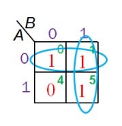
Figure 1. K-map for A implies B implication logic
The implication function can be realized using a relatively simple circuit comprising of a combination of memristors and a conventional resistor. This logic can effectively function as a non-volatile memory as depicted in this research paper by S K Vatinsky et al.
Inhibition
The inhibition function is the complementary version of implication and thus has its truth table as defined by Table 4 for A inhibits B case.
| Inputs | Output | |
| A | B | Y |
| 0 | 0 | 0 |
| 0 | 1 | 0 |
| 1 | 0 | 1 |
| 1 | 1 | 0 |
Table 4. Truth table of inhibition logic for A inhibits B case
With this, the logic expression for the function would result as \(A \bullet \bar {B}\) as shown by the K-map of Figure 2.
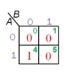
Figure 2. K-map for A inhibits B inhibition logic
Likewise, for B inhibits A, the expression would be \(\bar {A} \bullet B\). Application of inhibition logic in the field of artificial neural networks is explained in detail in the Springer supplement authored by R. Rojas.
Conclusion
Every Boolean function has its own meaning and serves a purpose. Widespread use of a few of them need not necessarily imply that the others are not also useful.