
Creating a DCO-based Audio Synthesizer With an Arduino Nano
In this project, learn to create a digitally-controlled oscillator or DCO-based audio synthesizer with an Arduino Nano or an Arduino Uno.
I love music, and I also love electronics. For years, I’ve been building musical electronic devices, mostly in service to my electric guitar playing. After building and modifying a few tube amps and effects pedals, I decided to branch out into the realm of audio synthesis. I’ve often dreamed of creating my own Eurorack synthesizer, one module at a time, but for my first synthesizer project, I decided to start with a stand-alone keyboard. My finished product—a modified toy keyboard—is shown in Figure 1.

Figure 1. The modified and vastly improved “Rockstar” keyboard.
In this project, I removed the existing electronics and replaced them with a digitally-controlled oscillator (DCO)-based audio synthesizer with an Arduino Nano at its heart. Though I used an Arduino Nano, an Arduino Uno can also be used. Let's dive into how we can make a DCO-based synthesizer. However, before going too far, let's first talk about the use of an oscillator in a synthesizer.
The Oscillator: The Heart of Any Synthesizer
The key element of any synthesizer is its oscillator circuitry. Analog synthesizers usually have two or more independently controllable oscillators. However, anyone who has stepped into the internet rabbit hole of an analog voltage-controlled oscillator (VCO) schematics knows that they are usually complicated and cluttered. Some of the clutter comes from features that can be disposed of gracefully, such as multiple control voltage inputs. However, even when the simplest oscillator circuit is isolated within a schematic, what remains is still complicated by thermal feedback tricks to keep the oscillator in tune as its components warm up.
The complexity and clutter of VCO circuits have always been a stumbling block for me when I have considered creating my own synthesizer, and even though I love analog synthesis, I haven’t been able to get past its messy electronic underbelly. That all changed when I gained an appreciation for the Roland Juno line of synthesizers.
Roland’s Juno-6 hit the market in 1982 as a more affordable alternative to other polyphonic synthesizers available at the time. It also was the first synthesizer to utilize DCOs instead of the traditional VCOs. This dramatically improved the tuning stability of the instrument compared to alternatives because DCOs use digital circuitry to govern the frequency of the oscillator’s analog signal. With that in mind, there are certainly tradeoffs to using DCOs instead of VCOs, of course. Many folks love the “warm” sound of two slightly detuned VCOs playing in unison, which is difficult to emulate with a DCO-based synthesizer. However, modulation effects can be applied to the dry output signal from a DCO to produce lush, beautiful sounds.
Overall, the ubiquity and low cost of the Arduino Uno and Nano development boards, coupled with the fact that those digital platforms come pre-equipped with 16 MHz crystal oscillators, make creating a DCO on the cheap incredibly easy.
Creating a DCO With a Microcontroller Timer Module
Look at the datasheet for any modern microcontroller, and you will find a timer module among its peripherals. A timer module allows an embedded designer to set up a running counter in the background of an embedded system that is independent of the CPU (central processing unit). Moreover, timer modules can interrupt the CPU under numerous conditions, such as when they overflow their count register or when they reach a certain count. The interrupt conditions can be configured by the embedded designer to meet the needs of their specific application.
For this project, the timer modules of the ATMega328P—the brain of the Arduino Nano and Uno—act as the DCOs of the synthesizer. By configuring the clock source and the maximum count value for a timer module, timer module interrupts can be triggered at audio frequencies. DCO output is achieved by manipulating the GPIO pins of the microcontroller during the interrupt service routines (ISRs) for these periodic interrupts.
In the following sections, I will discuss the hardware and software design behind this project and then present some audio clips from this homemade synthesizer.
Hardware for an Audio Synthesizer Using an Arduino Nano
Before getting into the different hardware involved in this project and how it all works together, Table 1 shows the BOM (bill of materials).
| Quantity | Component |
|---|---|
| 1 |
Arduino Nano v3.x |
| 4 | 470 nF capacitor |
| 1 | 2.1 mm barrel jack |
| 1 | 1/4" mono switch jack |
| 2 | 4.7k resistor |
| 3 | 47k resistor |
| 7 | 100k resistor |
| 1 | 100k resistor |
| 2 | 100k potentiometer |
| 1 | 1 M potentiometer |
| 23 | SPDT micro momentary switch |
| 1 | Switching DC-DC converter (5 V output) |
| 1 | Microchip MCP23017 I/O extender |
| 1 | LF411 operational amplifier (op amp) |
Next, let's look at the system diagram of Figure 2, which shows how the pieces of this synthesizer are all combined.

Figure 2. Hardware system diagram for the synthesizer.
The keyboard section is comprised of an array of 23 SPDT switches, one for each key. Sixteen of those keys are routed into an MCP23017 I/O extender, and the remaining 7 keys are routed directly to GPIO inputs on the Arduino Nano. The MCP23017 is then connected to the Arduino Nano via I2C.
From here, the Arduino Nano processes the input from the keyboard and generates three independent oscillator outputs on D11, D12, and D10 based on those key presses. The outputs from those digital pins on the Arduino Nano are routed into a summing amplifier circuit, the schematic of which is shown in Figure 3.
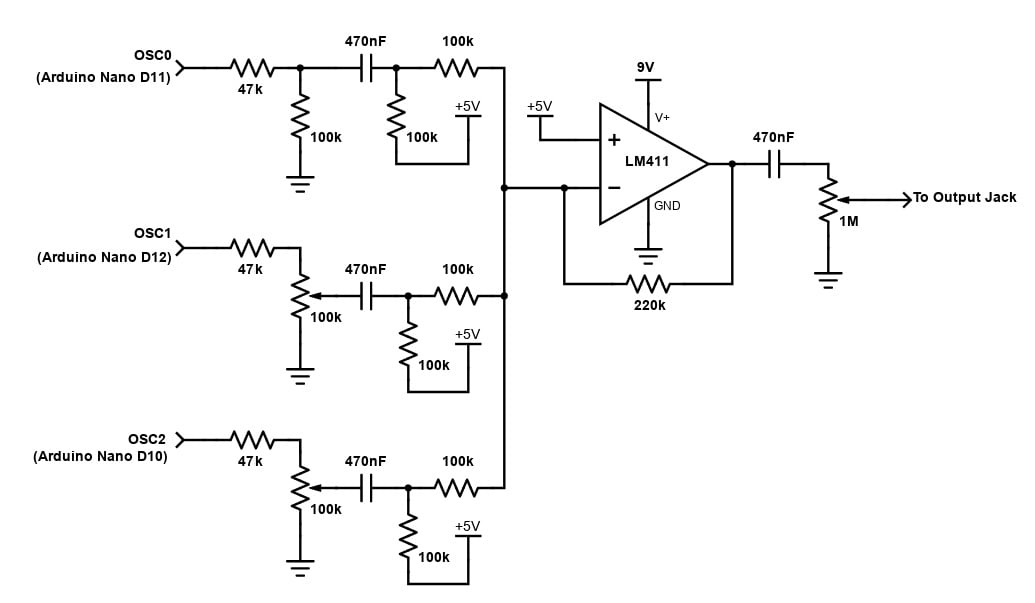
Figure 3. Schematic of the summing amplifier circuit [click image to enlarge].
The summing amplifier incorporates three potentiometers. These control the volumes of oscillators 2 and 3 independently and the master volume of the instrument. The output of the amplifier circuit is routed directly to a ¼” mono audio jack, making it easy to plug directly into a guitar amplifier.
To power this instrument, I use a standard 2.1 mm 9 V DC guitar pedal barrel jack. Additionally, the +9 V from that jack is routed to a small DC-DC switching power converter to generate a 5 V power connection. The +5 V supply powers the MCP23017. The Arduino is powered through its Vin pin by the +9 V supply. V+ and V- for the op-amp are provided by the +9 V and ground connections from the barrel jack, and the 5 V supply is used as a floating ground connection for the op amp.
A schematic showing how all pieces of this system are connected is shown in Figure 4.

Figure 4. Schematic of the entire system [click image to enlarge].
Software Aspects of Creating an Audio Synthesizer
The main task of the software for this project is to interpret inputs from the keyboard buttons and manipulate timer module registers accordingly (see the Arduino sketch PDF here for the code). Before the setup() function in the sketch, several global variables are declared, including two large, 2D arrays of timer module register values corresponding to musical notes. The procedure of the setup() function follows the flow diagram of Figure 5, which simply involves:
- Setting up the GPIO inputs and outputs
- Starting I2C communication
- Initializing the three timer modules
- Enabling interrupts
- Choosing the clock source for the Timer B modules to be the clock for Timer A
- Enabling global interrupts

Figure 5. Flow diagram for the setup() function of the Arduino sketch for this instrument.
A flow diagram representing the loop() function for the Arduino sketch is shown in Figure 6.

Figure 6. Flow diagram for the loop() function of the Arduino sketch for this instrument [click image to enlarge].
The loop function performs three main tasks:
- Detecting a pressed key on the keyboard
- Setting timer module parameters based on the note of that particular key
- Setting the gate variable to allow oscillator signals to be forwarded to their respective GPIO pins
The loop function evaluates each I/O port that is connected to the keyboard one at a time until a pressed button is detected. The order of evaluation of the ports is from lowest note to highest note on the keyboard, which means lower notes effectively have a higher priority. While I considered using GPIO and I2C interrupts to handle keyboard button presses, I ended up using a continuous polling approach, and I haven’t noticed any detrimental performance as a result.
Finally, Figure 7 represents the interrupt service routines for each of the three timer modules in the ATMega328P.

Figure 7. Flow diagram for the interrupt service routines for the Arduino Nano’s ATMega328P timer modules.
Each of these ISRs toggles its output pin value if the gate variable is set. This toggling is what generates the audio frequency output for each oscillator.
The Resulting Sound Samples and Potential Enhancements
Below you can find two audio samples from this project. Be sure to click on the play button image to play—note that the audio will open and play on a separate window.

Sound clip 1. Audio synth demo.
As you can hear from the first audio sample, this synthesizer produces a pretty spartan, lo-fi sound. That sample demonstrates first the root note oscillator, then the root note and the octave down oscillators, and finally the root note, octave down, and 7 semitones up oscillators.
Sound clip 2. Audio synth demo with effects and drums.
The second sample shows off the synthesizer through some delay and phasing effects, with multiple tracks overlaid. All the melodic sounds are from the Arduino synth, but the drum sounds are from a Roland 808-style drum machine vst plugin.
All in all, I am thrilled with the results of this project, but I do think there are many potential improvements that could be implemented with this Arduino-based synthesizer. For example, I would like to implement a USB midi interface for this Arduino synth. I would also like to create an expandable poly synth using these methods. However, as it stands, the toy housing this project has been transformed into is a fun, stage-worthy, lo-fi instrument with a seriously gritty bass sound.
If you choose to build your own Arduino-based synth like this, let me know in the comments down below how it sounds. Good luck, and keep making noise!


Thanks for sharing your work! I want to mention, that the term DCO usually describes an oscillator that is based on charging a capacitor (like in a classic VCO), but the charge/discharge cycle is digitally controlled. In your design, the name “numerically controlled oscillator” or simply digital oscillator would be more correct.
It’s a keyboard controller and digital oscillator with an amplifier. It’s not a digitally controlled oscillator.