
Small Size, nanoPower: A New Comparator from Texas Instruments
This article will look at the most important features of the TLV7031 which is a nanoPower comparator from Texas Instruments.
This article will look at the most important features of the TLV7031 which is a nanoPower comparator from Texas Instruments. Two possible applications for this low-power device will be briefly discussed.
The TLV7031 has a quiescent supply current of 335 nA and its input bias current is 2 pA. The nanoPower device exhibits a propagation delay of 3 seconds and is provided in the tiny packages shown in Figure 1. The device is suitable for space-critical designs like smartphones. Additionally, the device can be used in very low-power applications that require nanoPower: threshold detectors, IR receivers, etc.
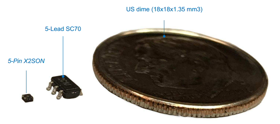
Figure 1. Image courtesy of Texas Instruments.
The Functional Block Diagram
The functional block diagram of the TLV7031 is shown in Figure 2.
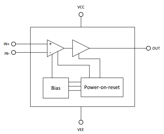
Figure 2. Image courtesy of Texas Instruments.
The device incorporates a rail-to-rail input stage that can accept a common-mode value from $$V_{EE}$$ to 100 mV above $$V_{CC}$$. The input bias current is about 2 pA. Even when the device is not powered or its supply is ramping up, the input still exhibits a high impedance.
The TLV7031 has a push-pull output but its sister device, the TLV7041, provides an open-drain output. The open-drain output configuration could be used to change the voltage level representing the logic high at the device output. This can be done by pulling the output to an external supply rail independent from the device supply voltage. The open-drain feature could also be used to connect the output of several TLV7041s together to form a wired-OR logic gate.
The supply voltage of the TLV7031 ranges from 1.6 V to 6.5 V. The block diagram in Figure 2 shows that the device has a “Power-on-reset” (POR) module that is connected to the device “Bias” circuit. If the supply voltage goes below the minimum acceptable value, i.e. 1.6 V, the POR circuit gets activated and sets the output of the TLV7031 to logic low. For a TLV7041 device, the output will be high impedance when the POR circuit is activated. Note that these comparators have a power-up time of $$t_{ON}=200 \; \mu s$$. Hence, during power-up, the supply voltage must be above 1.6 V for about $$200 \; \mu s$$ before the comparator output can produce a valid result. This is shown in Figure 3. In this example waveform, we have $$V_{IN+} > V_{IN-}$$.
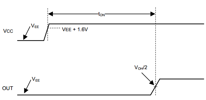
Figure 3. Power-up time of the comparator. Image courtesy of Texas Instruments.
Now, let’s look at two example applications for these nanoPower comparators.
Infrared Receiver Analog Front End
Infrared (IR) communication can be an interesting solution when there’s a line-of-sight path between the transmitter and the receiver. This communication technique is not only low-cost but also immune to RF interference. These advantages make the IR communication suitable for applications such as hermetically sealed utility metering. In this application, minimizing the system power consumption can help us to increase the battery life and, consequently, reduce the cost of maintenance. To minimize the power consumption, we can use the scheme depicted in Figure 4. The low-power analog front end (AFE) is constantly powered but the host microcontroller (MCU) is in the shut-down power state. When a valid IR signal is received, the AFE wakes up the MCU.
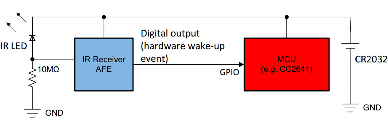
Figure 4. Image courtesy of Texas Instruments.
The circuit implementation of the idea shown above is depicted in Figure 5.
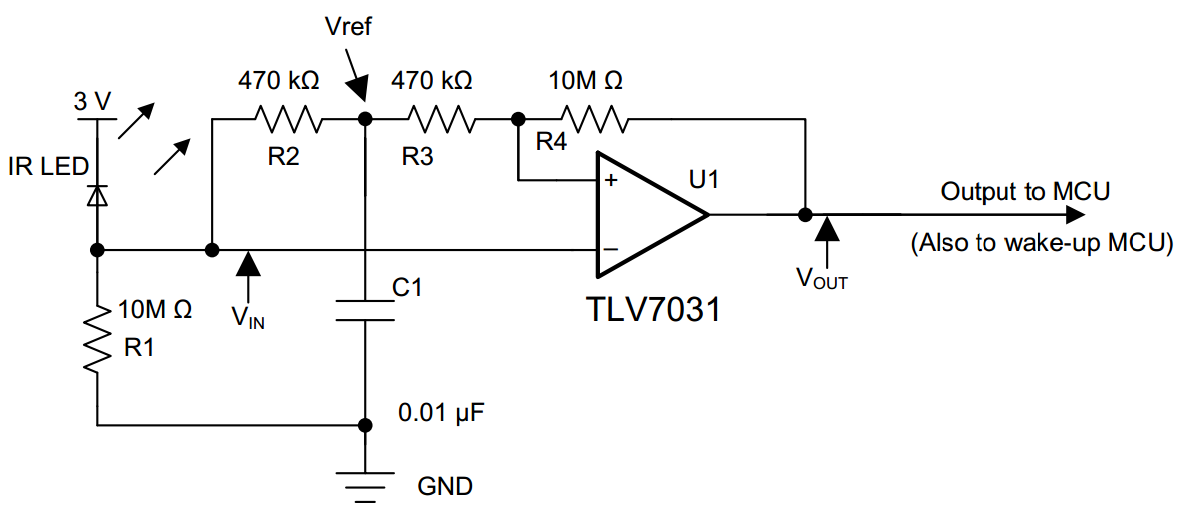
Figure 5. Image courtesy of Texas Instruments.
This circuit, presented by TI, uses an IR LED emitter instead of a receiver to reduce cost at the expense of sensitivity. When IR light strikes the LED, the photoelectric effect frees electrons in the LED, creating a current.
The current induced by the incident IR light goes through resistor R1 and generates a voltage signal. This voltage is applied to the inverting input of the TLV7031. R2 and C1 form a lowpass filter which determines the mean amplitude of the incident IR signal. This mean value is connected to the non-inverting input of the comparator through the R3 resistor. In fact, the RC network gives us a threshold that automatically adapts to the ambient light level.
The positive feedback loop formed by R4 and R3 produces a hysteresis effect in addition to the internal hysteresis of the TLV7031 (See the datasheet for more details). The hysteresis prevents the output from spurious toggles. The waveforms for the IR receiver AFE are shown in Figure 6.
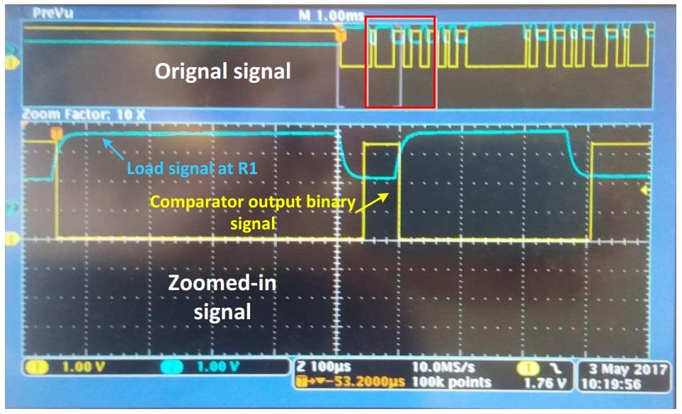
Figure 6. Image courtesy of Texas Instruments.
Figure 41 of the device datasheet gives the following waveforms for the IR receiver AFE. Note that this curve is not correct because $$V_{OUT}$$ must have a phase shift of $$180^{\circ}$$ relative to the $$V_{IN}$$ signal shown in Figure 5.
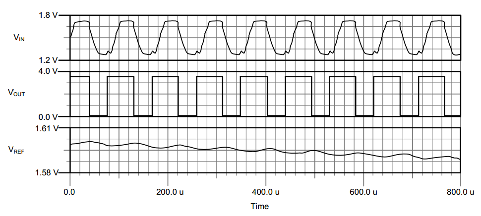
Figure 7. Image courtesy of Texas Instruments.
For the IR receiver AFE, two features of the TLV7031 are important:
- low quiescent supply current ( about 335 nA )
- low input bias current (2 pA)
The first feature allows us to have a nanoPower comparator. The second one allows us to increase the value of R1 without sacrificing linearity. Consequently, a larger R1 leads to a smaller supply current drawn by the LED-R1 branch.
Window Comparator
As shown in Figure 8, we can use two TLV7041 devices to establish a window comparator.
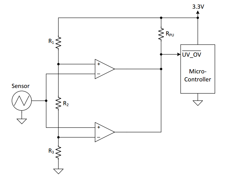
Figure 8. Image courtesy of Texas Instruments.
This circuit creates two thresholds using a resistive voltage divider formed by the R1, R2, and R3 network. The low threshold applied to the inverting input of the the lower TLV7041 is
$$V_{th, low}= \frac{R_3}{R_1+R_2+R_3}\times 3.3 \; V$$
The high threshold applied to the non-inverting input of the upper comparator is
$$V_{th, high}= \frac{R_2+R_3}{R_1+R_2+R_3}\times 3.3 \; V$$
We have three cases:
- When the sensor output is below $$V_{th, \; low}$$, the lower TLV7041 sets the output to logic low. The other comparator is in the high impedance state in this case.
- When the input is above $$V_{th, \; low}$$ and below $$V_{th, \; high}$$, both of the comparator outputs are high impedance. Hence, the output is pulled up by the RPU resistor.
- When the input is above $$V_{th, \; high}$$, the upper TLV7041 sets the output to logic low. The other comparator is in the high impedance state in this case.
Therefore, when an undervoltage or an overvoltage condition occurs, the output of the window comparator is set to logic low and the microcontroller is alerted. Note that the open-drain feature of the TLV7041 allowed us to safely connect the output of the two devices together.
Another interesting application for the TLV7041 device is in headphone jack detection. See this TI document for details.
In this article, we looked at some of the important features of the TLV7031 and TLV7041. We also briefly discussed two application examples for these comparators. If you have any experience with these comparators or other similar parts, please let us know in the comments below.


