
The Kikusui Battery Emulator System With the PXB Programmable Power Supply
Battery characteristics constantly change due to the battery’s state of charge (SOC) and temperature, making it difficult to conduct a stable and reproducible battery evaluation test. Because of the limited energy of a battery, manually adjusting the SOC using a charger is time-consuming. Battery emulators help solve these issues by operating according to any I-V characteristic without the need for a battery or charger.
The battery emulator system offered by Kikusui uses the SD036-PXB software in tandem with the PXB high-capacity bidirectional DC power supply to easily reproduce specific battery conditions.
This article dives into the need for battery emulators, the different tests that can be performed with these systems, and how the Kikusui battery emulator system can be used to simulate a battery when testing a wide variety of equipment under test (EUT) including eAxles, motors, onboard chargers, and more.
The Need for Battery Emulators
Testing systems that interface with batteries requires understanding how the circuit operates with the changing internal resistance (IR) of the battery itself. An ideal battery will operate as a voltage source with a constant voltage supplied and zero IR, allowing for maximum current flow without any loss in loss. Every battery contains an internal resistance (IR) that is defined by its internal electrodes and type of electrolyte, creating a slope in its I-V curve. Instead of an ideal slope of zero, the internal resistance will create a definable slope in the curve where a higher IR will result in a steeper slope (Figure 1).
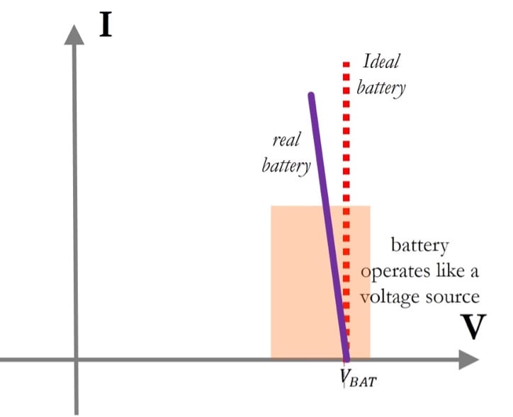
Figure 1. Simple diagram of the I-V characteristic of a battery with a slope defined by its IR. Image source: All About Circuits
A well-behaved battery will exhibit a low IR to deliver the required power spikes on demand (and extended battery runtime). However, shifts in a battery’s IR can occur due to calendar and cyclic aging; temporary fluctuations in IR can also occur with ambient temperature changes and even SOC variations as shown in Figure 2.

Figure 2. The variation in IR different discharge currents and SOC levels of a Li-ion battery. Image source: [1]
The variability in the power a battery supplies must be effectively reproduced when testing EUTs such as battery management systems (BMS), chargers (e.g., OBCs, DC chargers, etc.), and solar inverters/charge controllers, etc. Using a real battery to do this testing is time-consuming—batteries must first be charged, discharged to a desired SOC, and then allowed to rest to finally begin testing. The rest period is necessary as the optimal IR does not occur immediately after fully charging a battery but after a several-hour-long rest period, accounting for the largest waiting period. A rest period is also necessary after discharge (i.e., right before charging the battery). This process is difficult to follow on a small scale and grows in complexity on a larger scale. Battery emulators will mimic these I-V characteristics with a varying IR, for example, by setting the I-V curve according to the remaining SOC of the battery.
Conventional Battery Emulators
A more traditional battery emulator setup can be seen in Figure 3, with a separate power supply and electronic load used to emulate the battery charge and discharge cycles. This process requires a tight synchronization between both pieces of equipment to ensure a battery’s source and sink characteristics emulated without interruptions to accurately characterize/validate EUTs. Some test setups will also require an additional charge/discharge system, adding further complexity to battery emulation.
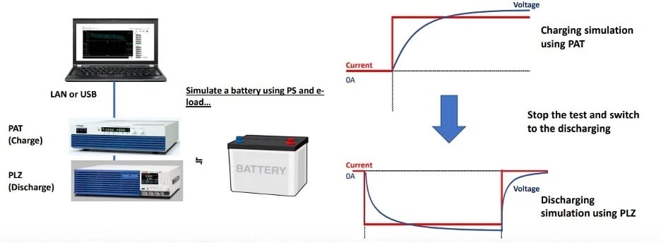
Figure 3. Conventional battery emulator using the Kikusui PAT constant voltage/constant current, auto-shifting, switching DC power supply to simulate charging, and the Kikusui PLZ multifunctional electronic load to simulate battery discharging. Image source: Kikusui Electronics
The Kikusui Battery Emulator System
The Kikusui battery emulator system uses the PXB bidirectional programmable power supply that effectively replaces both the power supply and electronic load in conventional battery emulators. This power supply can act as both a source and a sink to simulate battery charge and discharge between the simulated battery and circuit/EUT. As shown in Figure 4, the SD036-PXB software allows users to easily program the PXB to emulate battery charge/discharge operation based on I-V data.
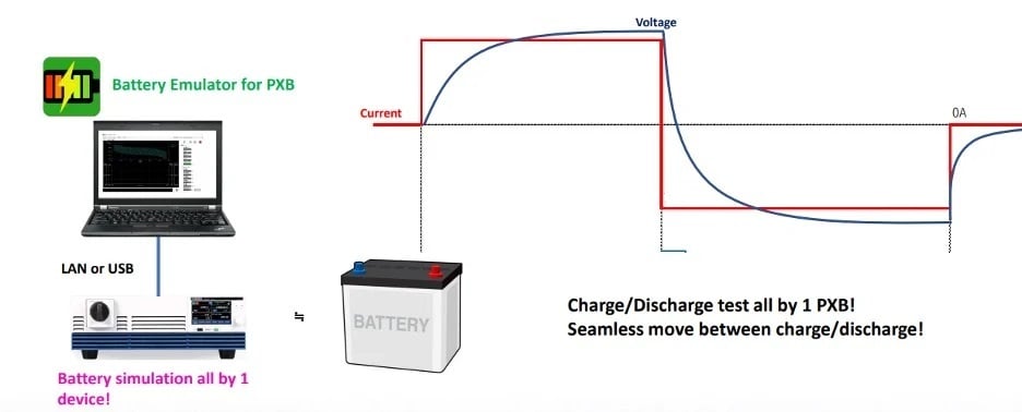
Figure 4. The SD036-PXB application software easily reproduces battery behavior using the PXB series. Image source: Kikusui Electronics
Benefits of the Kikusui Battery Emulator System
The battery emulator instantly cuts down most testing time associated with resting periods as well as the tracking required to monitor the necessary resting periods for multiple batteries in different set ups. Battery emulators allow the flexibility to simulate practically any battery regardless of chemistry or capacity, simplifying time to set up a reliable production test for different EUTs and associated battery systems. When a lab is equipped with a battery emulator, designing the battery unit in advance is not necessary; instead, development of the battery unit and the EUT can be performed in parallel, lowering the time to market.
Another benefit that may not be considered is the inherent risk that comes with housing large amounts of batteries—if not stored properly or mishandled these devices can experience thermal runaway and explosion, an eventuality with potentially catastrophic consequences. Industrial facilities that house batteries must take appropriate measures to ensure the safety of their personnel and plant equipment. These precautions come with added considerations and costs eliminated by employing battery emulators.
The Kikusui battery simulator system with the PXB has additional benefits over conventional battery emulators. The PXB and a laptop with SD036-PXB software enabled removes the need for the power supply, electronic load, and charge/discharge system controller.
An Intro to the Kikusui Battery Emulator System
Main Functions
The battery emulator system allows users to:
- Load custom I-V tables in a CSV format to the PXB
- Create interpolated I-V sheets for each SOC from the loaded I-V table file
- Perform voltage control using measured current values and I-V tables
- Enable the I-V curve graph to display for each SOC
- Display real-time measured values and graphs
- Generate a definable SOC or capacity at the start of operation
- Create custom stopping conditions based upon a predetermined SOC range
- Protect against any operation outside the I-V table
- Create log files
The system comes with a USB dongle that contains a sample I-V file of a SOC from 20% to 90% for the 500 V, 1000 V, and 1500 V versions of the PXB (Figure 5). Users can reuse/modify this file to create a custom I-V file that suits the EUT to conduct an emulation.
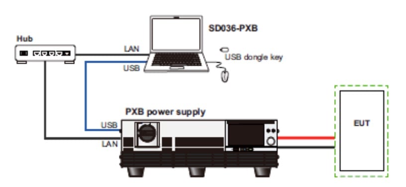
Figure 5. Kikusui battery emulator block diagram with PXB bidirectional power supply. Image source: Kikusui Electronics
Functions and Specifications
Reproducing specific battery conditions for testing is a difficult task to accomplish with real batteries. To test at every SOC, multiple batteries must be prepared with the proper charge, discharge, and rest time (Figure 6).

Figure 6. Preparing multiple batteries at different SOCs to begin performing EUT validation. Image source: Kikusui Electronics
This becomes even more complex with repetitive testing as the number of batteries must be scaled up to perform the test. As shown in Figure 7, the Kikusui battery emulator can simulate a battery at any SOC based upon the I-V characteristic data; this can be easily used for repetitive testing on EUTs for safety compliance and reliability (e.g., MTTF, MTBF, MTTR, etc.). The system also enables operation margin tests and failure analysis with battery deterioration or low charging conditions.
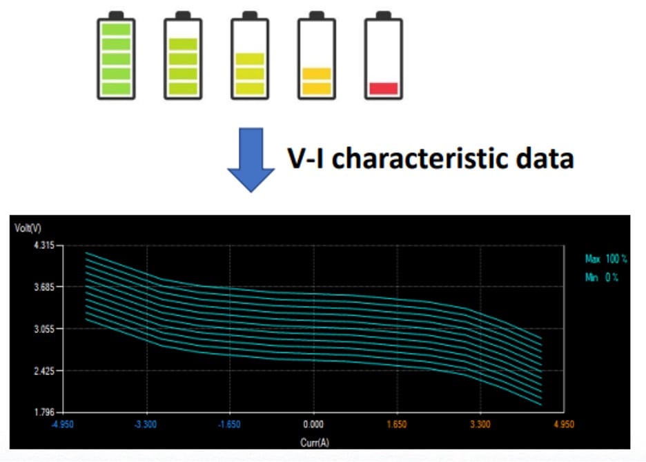
Figure 7. Instead of setting multiple batteries to different SOCs, the battery emulator will simulate the battery at specific SOCs with the I-V characteristic data. This data can be used to perform repetitive testing. Image source: Kikusui Electronics
However, if data is only available for 0% and 100% SOC the auto interpolation function will automatically create data for all SOCs in between with a minimum resolution of 1% (Figure 8).

Figure 8. The auto-interpolation function will automatically fill data between 0% and 100% SOC so testing can begin as rapidly as possible. Image source: Kikusui Electronics
Even data within the original I-V file can be auto-interpolated (Figure 9) — a file with 13 points of data is expanded to 60 data points with a resolution of 0.1 A.

Figure 9. Data interpolation can also be performed within an I-V data file. Image source: Kikusui Electronics
This ability simplifies the process of creating and expanding an exhaustive dataset for battery emulation to begin testing more rapidly. Kikusui uses both horizontal and vertical interpolation techniques. If the values within an established I-V file are further apart than 0.1 A, the battery emulator fills in the data between two points with linear interpolation (Figure 10). For vertical interpolation (refer to Figure 8), the battery emulator generates an interpolated I-V files at 1% increments with the requirement that data can only be generated when the current ranges of the upper and lower data match.

Figure 10. Horizontal and vertical interpolation processes used to fill in data with the battery emulator system. Image source: Kikusui Electronics
During operation, the SOC is calculated from the charge/discharge current and present nominal capacity of the battery. As shown in Figure 11, for SOCs that change with time (e.g., during discharge), the interpolated I-V file that corresponds to the SOC is selected and emulation is performed.

Figure 11. An example of a battery discharge performed by the emulator where interpolated I-V files are selected based upon the expected SOC over time. Image source: Kikusui Electronics
The user interface and display can be seen in Figure 12 with the interpolated I-V curve as well as the voltage, current, power, and SOC plotted over time.

Figure 12. Display (left) and user interface (right) where the real-time monitor will display voltage, current, power, and SOC data over time. Image source: Kikusui Electronics
Conclusion
As the market of storage batteries continues to increase, so does the demand for evaluating battery-powered devices and components. The time taken to prep batteries for validating and characterizing battery-powered EUTs can be long, especially when taking into consideration the several hours that must elapse for rest after charging a battery to capacity. Battery simulators can be used in place of batteries to speed up testing time and remove the safety concerns that come with handling batteries.
However, more conventional battery emulator setups will require the tight coordination between two distinct pieces of equipment: the power supply and the electronic load. This dynamic often calls for an additional component: a charge/discharge controller.
The Kikusui Battery Emulator System removes the overhead that comes with using batteries and cuts in half the component count of traditional battery emulators. With the SD036-PXB software, the system can be quickly set up and scaled for larger systems where the PXB can be paralleled to output higher powers. Finally, data within I-V tables as well as between I-V files can be expanded through linear interpolation techniques. This ability allows users to quickly establish a dataset with a horizontal resolution of 0.1 A and curate files at all SOCs between 0% and 100% at 1% intervals.
